Toyota Sienna Service Manual: Installation
1. INSTALL ENGINE COOLANT TEMPERATURE SENSOR
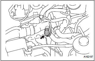
- Install the engine coolant temperature sensor.
Torque: 20 N*m (204 kgf*cm, 15 ft.*lbf)
- Connect the engine coolant temperature sensor connector.
2. INSTALL AIR CLEANER CASE SUB-ASSEMBLY
3. INSTALL AIR CLEANER CAP SUB-ASSEMBLY
4. INSTALL NO. 1 AIR CLEANER INLET
5. INSTALL NO. 2 AIR CLEANER INLET
6. ADD ENGINE COOLANT
7. INSPECT FOR ENGINE COOLANT LEAK
8. INSTALL V-BANK COVER SUB-ASSEMBLY
 Inspection
1. INSPECT ENGINE COOLANT TEMPERATURE SENSOR
Using an ohmmeter, measure the resistance
between the terminals.
Standard resistance
If the result is as specified, do not replace ...
 Knock sensor
COMPONENTS
...
Other materials:
On-vehicle inspection
1. INSPECT SIDE AIRBAG SENSOR (VEHICLE NOT
INVOLVED IN COLLISION)
Perform a diagnostic system check.
2. INSPECT SIDE AIRBAG SENSOR (VEHICLE
INVOLVED IN COLLISION AND AIRBAG HAS NOT
DEPLOYED)
Perform a diagnostic system check.
When the center pillar of the vehicle or ...
Clearance warning ECU
COMPONENTS
REMOVAL
1. REMOVE FRONT DOOR SCUFF PLATE LH
2. REMOVE COWL SIDE TRIM BOARD LH
3. REMOVE INSTRUMENT PANEL FINISH PANEL SUBASSEMBLY LOWER LH
4. REMOVE NO. 1 INSTRUMENT PANEL SAFETY PAD INSERT SUB-ASSEMBLY
5. REMOVE CLEARANCE WARNING ECU
Disconnect each connector.
&nb ...
Removal
1. REMOVE V-BANK COVER SUB-ASSEMBLY (See
page EM-28)
2. DISCONNECT VENTILATION HOSE
(a) Disconnect the ventilation hose from the ventilation
valve.
3. REMOVE VENTILATION VALVE
(a) Remove the ventilation valve. ...
