Toyota Sienna Service Manual: TC and CG Terminal Circuit
DESCRIPTION
DTC output mode is set by connecting terminals 13 (TC) and 4 (CG) of the DLC3. The DTCs are indicated by blinks of the tire pressure warning light.
WIRING DIAGRAM
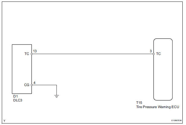
HINT: When each warning light blinks continuously, a ground short in the wiring of terminal TC of the DLC3 or an internal ground short in an ECU connected to this circuit may have occurred.
INSPECTION PROCEDURE
NOTICE: When replacing the tire pressure warning ECU, read the transmitter IDs stored in the old ECU using the intelligent tester and write them down before removal.
It is necessary to register an ID code after replacing the tire pressure warning valve and transmitter and/or the tire pressure warning ECU (See page TW-20).
1 CHECK HARNESS AND CONNECTOR (DLC3 - TIRE PRESSURE WARNING ECU)
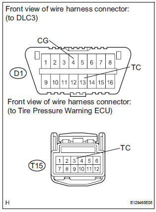
(a) Disconnect the T15 ECU connector.
(b) Measure the resistance according to the value(s) in the table below.
Standard resistance 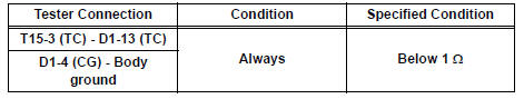


PROCEED TO NEXT CIRCUIT INSPECTION SHOWN IN PROBLEM SYMPTOMS TABLE (See page TW-28)
 ECU Power Source Circuit
DESCRIPTION
This is the power source for the tire pressure warning ECU.
WIRING DIAGRAM
INSPECTION PROCEDURE
NOTICE:
When replacing the tire pressure warning ECU, read the transmitter IDs
st ...
 Tire pressure warning receiver (w/ antenna)
Components
...
Other materials:
Dtc check / clear
Notice:All the stored dtcs and freeze frame data are
erased if:
1) the ecm is changed from normal mode to check mode
or vice versa; or 2) the ignition switch is turned from on
to acc or off while in check mode.
Before changing modes, always check and make a note
of any dt ...
Removal
1. REMOVE FRONT DOOR LOWER FRAME BRACKET GARNISH
2. REMOVE FRONT DOOR INSIDE HANDLE BEZEL PLUG
3. REMOVE FRONT DOOR ARMREST BASE PANEL
ASSEMBLY
4. REMOVE BACK FRAME PLATE
5. REMOVE POWER WINDOW REGULATOR MASTER SWITCH ASSEMBLY
6. REMOVE FRONT DOOR TRIM BOARD SUBASSEMBLY
7. REMOVE OUTER RE ...
Scratched / Reversed Disc
DTC 44-46 Scratched / Reversed Disc
DESCRIPTION
DTC No.
DTC Detecting Condition
Trouble Area
44-46
Scratches or dirt is found on DVD surface or DVD is set
upside down.
DVD
Television display assembly
INSPECTION PROCEDU ...
