Toyota Sienna Service Manual: Installation
1. INSTALL FRONT SHOULDER BELT ANCHOR ADJUSTER ASSEMBLY
- Install the front shoulder belt anchor adjuster
assembly with the bolt.
Torque: 42 N*m (430 kgf*cm, 31 ft.*lbf)
2. INSTALL CENTER PILLAR UPPER GARNISH
3. INSTALL FRONT SEAT OUTER BELT ASSEMBLY
NOTICE: Do not disassemble the retractor.
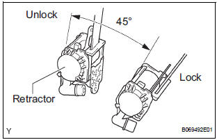
- Check the degree of tilt when beginning to lock the ELR.
- Check that the belt does not lock within 15
degrees of tilt in all directions but that the belt
locks with over 45 degrees of tilt, when gently
moving the retractor.
If operation is not as specified, replace the front seat outer belt assembly.
- Install the retractor with the 2 bolts.
Torque: 42 N*m (430 kgf*cm, 31 ft.*lbf)
- Install the shoulder anchor with the nut.
Torque: 42 N*m (430 kgf*cm, 31 ft.*lbf)
- Install the floor anchor with the bolt.
Torque: 42 N*m (430 kgf*cm, 31 ft.*lbf)
- Install the floor anchor cover.
- Check the ELR lock.
NOTICE: The check should be performed with the assembly installed.
- Check that the belt locks when pulling out the
belt quickly when the belt is installed.
If operation is not as specified, replace the front seat outer belt assembly.
- Check the fastening function of the child restraint system.
NOTICE: The check should be performed with the assembly installed.
- Check that the belt cannot be pulled out any more but can be rewound after the belt is fully pulled out.
- Check that the belt can be pulled out and
rewound after the belt is fully rewound.
If operation is not as specified, replace the front seat outer belt assembly.
4. INSTALL CENTER PILLAR LOWER GARNISH
5. INSTALL FRONT DOOR WEATHERSTRIP
6. INSTALL REAR DOOR WEATHERSTRIP
7. INSTALL FRONT DOOR SCUFF PLATE
8. INSTALL REAR DOOR SCUFF PLATE
9. INSTALL FRONT SEAT ASSEMBLY
HINT:
- Refer to the instructions for installation of the front seat assembly (for flat type).
- Refer to the instructions for installation of the front seat assembly (for manual seat).
- Refer to the instructions for installation of the front seat assembly (for power seat).
10. CONNECT CABLE TO NEGATIVE BATTERY TERMINAL
11. PERFORM INITIALIZATION
HINT: Some systems need initialization when disconnecting the cable from the negative battery terminal.
 Removal
1. DISCONNECT CABLE FROM NEGATIVE BATTERY
TERMINAL
CAUTION:
Wait for 90 seconds after disconnecting the cable to
prevent the airbag working.
2. REMOVE FRONT SEAT ASSEMBLY
HINT:
Refer t ...
 Disposal
1. DISPOSE OF FRONT SEAT OUTER BELT ASSEMBLY
(WHEN INSTALLED IN VEHICLE)
NOTICE:
Never dispose of a front seat outer belt assembly
with an deactivated pretensioner.
The seat belt ...
Other materials:
On-vehicle inspection
1. INSPECT SEAT POSITION SENSOR (VEHICLE NOT
INVOLVED IN COLLISION)
Perform a diagnostic system check.
2. INSPECT SEAT POSITION SENSOR (VEHICLE
INVOLVED IN COLLISION)
Perform a diagnostic system check.
Even if the airbag was not deployed, check if there
is any dama ...
Fuel Pump Control Circuit
DESCRIPTION
The FUEL PUMP relay switches the fuel pump speed according to the engine
conditions. The fuel pump
operates when the ECM receives the starter-operating signal (STA) and
crankshaft-rotating signal (NE).
The FUEL PUMP relay is turned ON while the engine is idling or operating at l ...
Road test
1. PROBLEM SYMPTOM CONFIRMATION
Inspect the SET function.
Turn the cruise control main switch on.
Drive at the required speed between 40 km/h
(25 mph) and 200 km/h (125 mph).
Push the cruise control main switch to -
(COAST)/SET.
After releasing t ...
