Toyota Sienna Service Manual: Disposal
1. DISPOSE OF FRONT SEAT OUTER BELT ASSEMBLY (WHEN INSTALLED IN VEHICLE)
NOTICE:
- Never dispose of a front seat outer belt assembly with an deactivated pretensioner.
- The seat belt pretensioner produces an exploding sound when it activates, so perform the operation outdoors where it will not create a nuisance to nearby residents.
- When activating a front seat outer belt assembly (with a seat belt pretensioner), perform the operation at least 10 m (33 ft) away from the front seat outer belt.
- Use gloves and safety glasses when handling a front seat belt with an activated pretensioner.
- Always wash your hands with water after completing the operation.
- Do not apply water, etc. to a front seat outer belt assembly with an activated pretensioner.
- When activating the seat belt pretensioner, always
use the specified SST (SRS airbag deployment
tool). Perform the operation in a place away from
electrical interference.
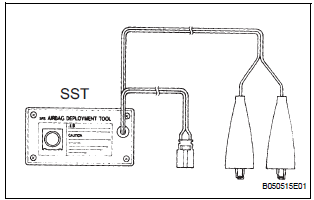
SST 09082-00700
HINT: When scrapping vehicles equipped with a seat belt pretensioner or disposing of a front seat outer belt (with a seat belt pretensioner), always activate the seat belt pretensioner first in accordance with the procedures described below. If any abnormality occurs during activation of the seat belt pretensioner, contact the SERVICE DEPT. of the DISTRIBUTOR.
- Disconnect the cable from negative battery terminal.
CAUTION: Wait for 90 seconds after disconnecting the cable to prevent the airbag working.
- Check the function of SST.
SST 09082-00700, 09082-00770
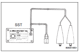
NOTICE: When activating the seat belt pretensioner, always use the specified SST.
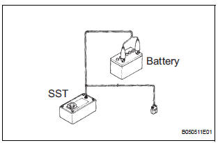
- Connect the SST red clip to the battery positive (+) terminal and the black clip to the battery negative (-) terminal.
HINT: Do not connect the yellow connector which will be connected to the seat belt pretensioner.
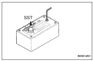
- Press the SST activation switch, and check that the LED of the SST activation switch lights up.
NOTICE: If the LED lights up when the activation switch is not pressed, the SST may have a malfunction. Therefore, do not use the SST.
- Disconnect the SST from the battery.
- Disconnect the pretensioner connector.
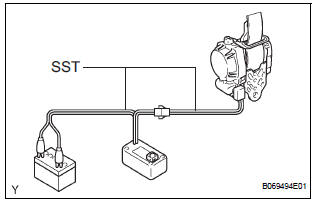
- Connect the SST.
- Install the floor anchor of the seat belt.
- Connect 2 SST, then connect them to the front seat outer belt pretensioner.
NOTICE: To avoid damaging the SST connector and wire harness, do not lock the secondary lock of the twin lock.

- Move the SST at least 10 m (33 ft.) away from the front of the vehicle.
- Close all the doors and windows of the vehicle.
NOTICE: Take care not to damage the SST wire harness.
- Connect the SST red clip to the battery positive (+) terminal and the black clip to the negative (- ) terminal.
- Activate the seat belt pretensioner.
- Confirm that no one is inside the vehicle or within 10 m (33 ft) of the vehicle.
- Press the SST activation switch and activate the seat belt pretensioner.
HINT: The seat belt pretensioner operates simultaneously with the LED light for the SST activation switch.
- Dispose of the front seat outer belt assembly (with the seat belt pretensioner).
NOTICE:
- The outer belt becomes very hot when the front seat outer belt pretensioner is activated, so leave it untouched for at least 30 minutes after it has been activated.
- Use gloves and safety glasses when handling an outer belt with a pretensioner that has been activated.
- Always wash your hands with water after completing the operation.
- Do not apply water, etc. to a front seat outer belt assembly with a pretensioner that has been activated.
HINT: When scrapping a vehicle, activate the front seat outer belt pretensioner, and then scrap the vehicle with the activated outer belt installed.
2. DISPOSE OF FRONT SEAT OUTER BELT ASSEMBLY (WHEN NOT INSTALLED IN VEHICLE)
SST 09082-00700, 09082-00770
NOTICE:
- When disposing of a front seat outer belt (with a seat belt pretensioner) only, never use the customers vehicle to activate the seat belt pretensioner.
- Be sure to follow the procedures listed below when activating the seat belt pretensioner.
- Remove the front seat outer belt.
- Check the function of SST.
NOTICE: When activating the seat belt pretensioner, always use the specified SST.
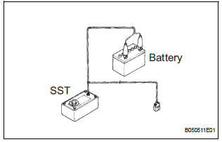
- Connect the SST red clip to the battery positive (+) terminal and the black clip to the battery negative (-) terminal.
HINT: Do not connect the yellow connector which will be connected to the seat belt pretensioner.
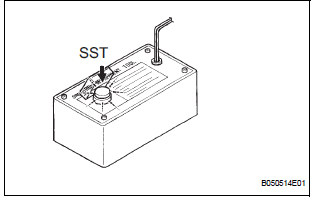
- Press the SST activation switch, and check that the LED of the SST activation switch lights up.
NOTICE: If the LED lights up when the activation switch is not pressed, the SST may have a malfunction. Therefore, do not use the SST.
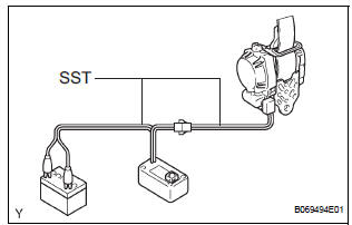
- Connect SST.
- Connect 2 SST, then connect them to the front seat outer belt pretensioner.
NOTICE: To avoid damaging the SST connector and wire harness, do not lock the secondary lock of the twin lock.
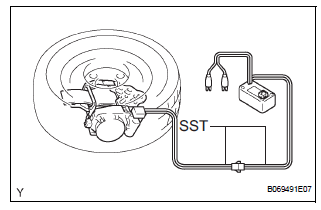
- Place the front seat outer belt assembly on the ground and cover it with a wheel with tire.
NOTICE: Set up the front seat outer belt assembly as shown in the illustration.

- Move the SST at least 10 m (33 ft.) away from the disc wheel.
NOTICE: Take care not to damage the SST wire harness.
- Activate the seat belt pretensioner.
- Connect the SST red clip to the battery positive (+) terminal and the black clip to the battery negative (-) terminal.
- Check that no one is within 10m(33 ft) of the wheel.
- Press the SST activation switch and activate the seat belt pretensioner.
HINT: The seat belt pretensioner operates simultaneously with the LED light for the SST activation switch.
- Dispose of the front seat outer belt (with the seat belt pretensioner).
NOTICE:
- The outer belt is very hot when the seat belt pretensioner is activated, so leave it untouched for at least 30 minutes after it has been activated.
- Use gloves and safety glasses when handling the front seat outer belt with the pretensioner that has been activated.
- Always wash your hands with water after completing operation.
- Do not apply water, etc. to an outer belt with the pretensioner that has been activated.
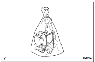
- Remove the wheel and SST from the front seat outer belt.
- Place the front seat outer belt in a plastic bag, tie the end tightly and dispose of it in the same way as other general parts.
 Installation
1. INSTALL FRONT SHOULDER BELT ANCHOR
ADJUSTER ASSEMBLY
Install the front shoulder belt anchor adjuster
assembly with the bolt.
Torque: 42 N*m (430 kgf*cm, 31 ft.*lbf)
2. INSTALL CEN ...
 Rear seat inner belt assembly
COMPONENTS
...
Other materials:
Canceling the power back door system (vehicles with power
back door)
Turn the main switch off to disable
the power back door system.
Off
On*
*: The orange line at the top of the
switch indicates that the power
back door system is on.
Luggage compartment light
The luggage compartment light turns on
when the back door is opened with the
luggage ...
Starter Relay Circuit High
MONITOR DESCRIPTION
While the engine is being cranked, the positive battery voltage is applied to
terminal STA of the ECM.
If the ECM detects the Starter Control (STA) signal while the vehicle is being
driven, it determines that
there is a malfunction in the STA circuit. The ECM then il ...
DTC check / clear
1. CHECK DTC
Connect the intelligent tester to the DLC3.
Connect the intelligent tester to the Controller
Area Network Vehicle Interface Module (CAN
VIM). Then connect the CAN VIM to the Data
Link Connector 3 (DLC3).
Turn the ignition switch to the ON posi ...
