Toyota Sienna Service Manual: Air Intake Control Circuit
DESCRIPTION
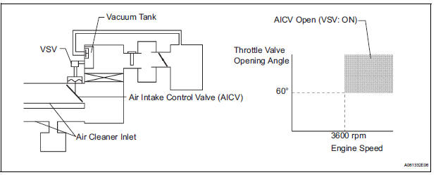
The air cleaner is equipped with two inlets, one of which is opened or closed by the Air Intake Control Valve (AICV). This system reduces intake noise and increases engine power at low-to-high engine speed range.
When the engine is operating in the low-to-mid speed range, this control operates the AICV to close one of the air cleaner inlets. When the engine speed is more than 3600 rpm and the opening angle of the throttle valve is more than 60°, the ECM activates the VSV and opens the AICV.
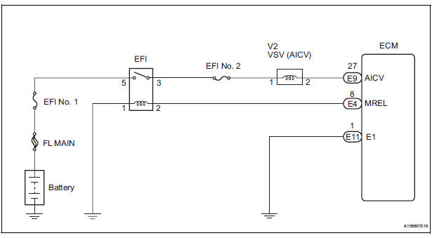
WIRING DIAGRAM
INSPECTION PROCEDURE
1 PERFORM ACTIVE TEST BY INTELLIGENT TESTER (VSV FOR AICV)
(a) Turn the ignition switch to the ON position and turn the intelligent tester on.
(b) Select the following menu items: DIAGNOSIS / ENHANCED OBD II / ACTIVE TEST / INTAKE CTL VSV1 and operate the VSV for AICV.
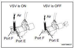
(c) Check the operation of the VSV when the VSV is operated by the intelligent tester.
Standard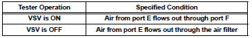


2 CHECK VSV (FOR AICV)
(a) Inspect the intake air control valve assembly (See page IT-8).

3 CHECK HARNESS AND CONNECTOR (VSV FOR AICV - ECM)
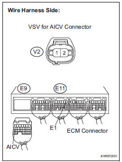
(a) Check the wire harness between the VSV for AICV connector and the ECM connector.
Standard resistance: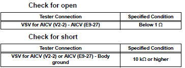
(4) Reconnect the ECM connector.

4 INSPECT FUSE (EFI NO. 2 FUSE)
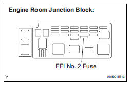
(a) Check the EFI No. 2 fuse.
(1) Remove the EFI No. 2 fuse from the engine room junction block.
(2) Measure the EFI No. 2 fuse resistance.
Standard resistance: Below 1 Ω
(3) Reinstall the EFI No. 2 fuse.

5 CHECK HARNESS AND CONNECTOR (VSV FOR AICV - EFI RELAY)
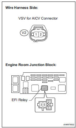
(a) Check the wire harness between the VSV for AICV and the EFI relay.
(1) Remove the EFI relay from the engine room junction block.
(2) Measure the resistance according to the value(s) in the table below
Standard resistance :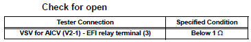
(3) Reconnect the VSV for AICV connector.
(4) Reinstall the EFI relay.

6 INSPECT VACUUM TANK
(a) Inspect the vacuum tank (See page IT-6).

CHECK ECM POWER SOURCE CIRCUIT
 ACIS Control Circuit
DESCRIPTION
This circuit opens and closes the Intake Air Control Valve (IACV) in response
to changes in the engine
load in order to increase the intake efficiency (ACIS: Acoustic Control
Inducti ...
 MIL Circuit
DESCRIPTION
The MIL (Malfunction Indicator Lamp) is used to indicate vehicle malfunctions
detected by the ECM.
When the ignition switch is turned to the ON position, power is supplied to the
M ...
Other materials:
Short in Rear Curtain Shield Squib RH Circuit
DTC B1630/83 Short in Rear Curtain Shield Squib RH Circuit
DESCRIPTION
The rear curtain shield squib RH circuit consists of the center airbag sensor
assembly and the curtain
shield airbag assembly RH.
The circuit instructs the SRS to deploy when deployment conditions are met.
DTC B1630/83 ...
Short to B+ in Front Passenger Side Squib Circuit
DTC B0108/52 Short to B+ in Front Passenger Side Squib Circuit
DESCRIPTION
The front passenger side squib circuit consists of the center airbag sensor
assembly and the front
passenger airbag assembly.
The circuit instructs the SRS to deploy when deployment conditions are met.
DTC B0108/52 ...
Right Front Wheel Speed Sensor Signal
DESCRIPTION
The speed sensor detects wheel speed and sends the appropriate signals to the
ECU. These signals are
used to control the ABS control system. The front and rear rotors have 48
serrations each.
When the rotors rotate, the magnetic field emitted by the permanent magnet in
t ...
