Toyota Sienna Service Manual: Installation
1. Install heated oxygen sensor (for bank 2 sensor 2) (see page ec-34)
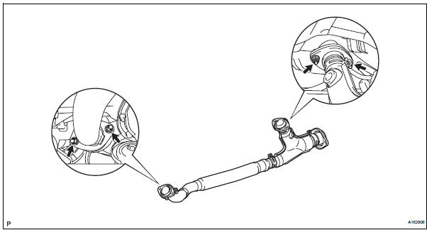
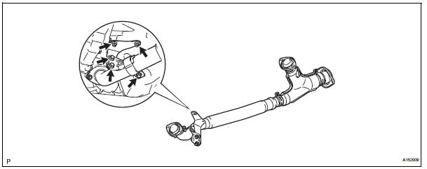
2. Install front exhaust pipe assembly
(a) Install 2 new gaskets to the front exhaust pipe assembly.
(b) Install the front exhaust pipe assembly with the 4 nuts.
Torque: 62 n*m (632 kgf*cm, 46 ft.*Lbf)
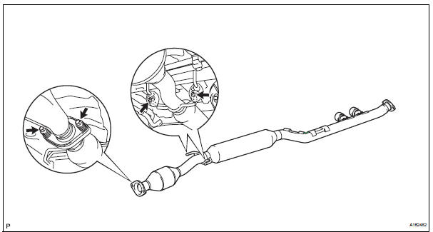
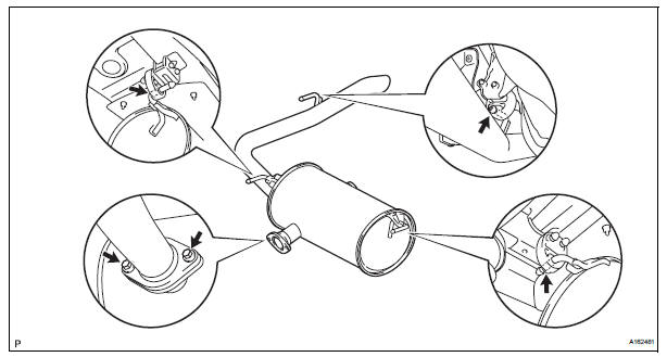
3. INSTALL CENTER EXHAUST PIPE ASSEMBLY
(a) Using a vernier caliper, measure the free length of the compression spring.
Minimum length: 38.86 mm (1.5299 in.)
If the length is less than the minimum, replace the compression spring.
(b) Install a new gasket by hand so that its surface is flush with the front exhaust pipe assembly.
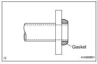
NOTICE:
|
(c) Connect the 2 exhaust pipe supports, and install the center exhaust pipe assembly.
(d) Install the 2 compression springs and 2 bolts.
Torque: 43 N*m (438 kgf*cm, 32 ft.*lbf)
(e) Connect the heated oxygen sensor (for bank 2 sensor 2) connector.
4. INSTALL NO. 1 EXHAUST PIPE SUPPORT BRACKET
(a) Install the No. 1 exhaust pipe support bracket to oil pan sub-assembly with 2 new nuts.
Torque: 21 N*m (214 kgf*cm, 15 ft.*lbf) (b) Loosen the No. 1 exhaust pipe support bracket bolts.
(c) Install the clamp to No. 1 exhaust pipe support bracket.
(d) Retighten the No. 1 exhaust pipe support bracket bolts.
Torque: 21 N*m (214 kgf*cm, 15 ft.*lbf) (e) Install the clamp with the bolt.
Torque: 21 N*m (214 kgf*cm, 15 ft.*lbf)
5. INSTALL TAIL EXHAUST PIPE ASSEMBLY
(a) Install a new gasket to the center exhaust pipe assembly.
(b) Connect the 3 exhaust pipe supports, and install the tail exhaust pipe assembly.
(c) Install 2 new bolts.
Torque: 43 N*m (438 kgf*cm, 32 ft.*lbf)
6. INSTALL HEATED OXYGEN SENSOR (for Bank 1 Sensor 2) (See page EC-36) 7. CONNECT CABLE TO NEGATIVE BATTERY TERMINAL
8. INSPECT FOR EXHAUST GAS LEAK
If exhaust gas is leaking, repair the leak. Replace damaged parts as necessary.
 Removal
1. Disconnect cable from negative battery
terminal
2. REMOVE HEATED OXYGEN SENSOR (for Bank 1
Sensor 2) (See page EC-32)
3. REMOVE TAIL EXHAUST PIPE ASSEMBLY
(a) Remove the 2 bolts.
(b) Discon ...
 Exhaust pipe (for 4wd)
Components
...
Other materials:
Engine Coolant Temperature Circuit Range / Performance Problem
DESCRIPTION
Refer to DTC P0115 (See page ES-133).
MONITOR DESCRIPTION
The ECT sensor is used to monitor the ECT. The ECT sensor has a built-in
thermistor with a resistance
that varies according to the temperature of the engine coolant. When the ECT
becomes low, the
resistance of the ...
Inspection
1. INSPECT OUTER REAR VIEW MIRROR ASSEMBLY LH (w/o Memory)
Disconnect the mirror connector.
Check operation of the outer mirror.
Apply battery voltage and inspect operation of
the mirror face, as shown in the table and
illustration.
Standard (LH)
If the result i ...
Glove boxes
Upper glove box
Push the button.
Open the lid.
Lower glove box
The lower glove box can be opened by pulling the lever and can be
locked and unlocked by using the master key (vehicles without a
smart key) or the mechanical key (vehicles with a smart key system).
Unlo ...
