Toyota Sienna Service Manual: Transmitter ID1 Error
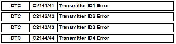
DESCRIPTION
The tire pressure warning valve and transmitters that are installed in the tire and wheel assemblies measure the air pressure of the tires. The measured values are transmitted to the tire pressure warning antenna and receiver on the body as radio waves and then sent to the tire pressure warning ECU. The ECU compares the measured air pressure values with the air pressure threshold. When the measured air pressure value is less than this threshold, the warning light in the combination meter comes on.
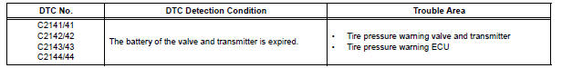
When the internal circuit of the tire pressure warning valve and transmitter is malfunctioning, this DTC is output.
HINT: It is necessary to perform the procedure to identify the tire pressure warning valve and transmitter that is malfunctioning because it cannot be identified by the output DTC.
INSPECTION PROCEDURE
NOTICE:
- When replacing the tire pressure warning ECU, read the IDs stored in the ECU using the intelligent tester and write them down before removal.
- It is necessary to perform initialization (See page TW-23) after registration (See page TW-20) of the transmitter IDs into the tire pressure warning ECU after the ECU and/or valve and transmitter have been replaced.
1 IDENTIFY TRANSMITTER CORRESPONDING TO DTC
(a) Set the tire pressure to the specified value.
Cold tire inflation pressure 
(b) Make sure that the ignition switch is off.
(c) Connect the intelligent tester to the DLC3.
(d) Turn the ignition switch to the ON position.
(e) Display the "TIREPRESS" data for each wheel using the intelligent tester.
(f) Rapidly reduce the tire pressure for each wheel at least 40 kPa (0.41 kg/cm2, 5.8 psi) within 30 seconds. If "TIREPRESS" displayed on the tester (ID1 to ID4) does not change, the tire pressure warning valve and transmitter corresponds to the DTC that was detected.
HINT:
- Identify the malfunctioning tire pressure warning valve and transmitter by repeatedly decreasing the tire pressure for each tire.
- Record which "TIREPRESS" data (ID1 to ID4) corresponds to each tire.
TIRE PRESSURE: 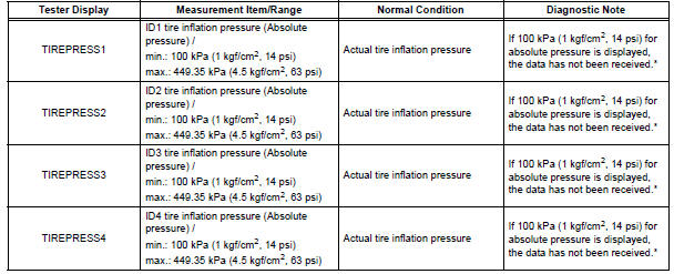
HINT: *: It may take about 5 to 6 minutes until the values are displayed. If the values are not displayed after a few minutes, perform troubleshooting according to the inspection procedure for DTCs C2121/21 to C2124/24 (See page TW-42).
(g) Check the DATA LIST.
Result 
NOTICE:
- When "TIREPRESS" data has not changed, reset the tire pressure to the appropriate specified value and rotate the tire 90 to 270 degrees. Then forcibly transmit the transmitter ID and recheck it.
- Record the transmitter ID and position of transmitters that are normal.
(h) When the "TIREPRESS" data (ID1 to ID4) has changed, repeat this procedure to identify the tire pressure warning valve and transmitter that corresponds to a DTC.
(i) When all of the "TIREPRESS" data (ID1 to ID4) have changed, identify the malfunctioning tire pressure warning valve and transmitter using recorded ID numbers and output DTC.
(j) Set the tire pressures to the appropriate specified values.

2 REPLACE TIRE PRESSURE WARNING VALVE AND TRANSMITTER
(a) Replace the identified tire pressure warning valve and transmitter with a new one (See page TW-84).
HINT:
- Before installing a new tire pressure warning valve and transmitter, read and write down its transmitter ID.
- The IDs for the tire pressure warning valve and transmitter which are not replaced should be checked using the tester and recorded.

3 REGISTRATION OF TRANSMITTER ID
(a) Register the transmitter ID for all wheels (See page TW- 20).

4 PERFORM INITIALIZATION
(a) Perform initialization (See page TW-23).
5 READ VALUE ON INTELLIGENT TESTER
(a) Make sure that the ignition switch is off.
(b) Connect the intelligent tester to the DLC3.
(c) Turn the ignition switch to the ON position.
(d) Select "TIREPRESS" by following the prompts displayed on the intelligent tester.
TIRE PRESSURE:
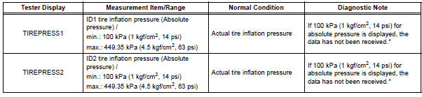
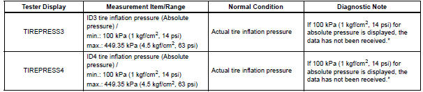
HINT: *: It may take about 5 to 6 minutes until the values are displayed. If the values are not displayed after a few minutes, perform troubleshooting according to the inspection procedure for DTCs C2121/21 to C2124/24 (See page TW-35).
Result

REPLACE TIRE PRESSURE WARNING ECU (See page TW-87)
 No Signal from Transmitter ID1
DESCRIPTION
The tire pressure warning valve and transmitters that are installed in the
tire and wheel assemblies
measure the air pressure of the tires. The measured values are transmitted to
...
 Abnormal Temperature Inside ID1 Tire
DESCRIPTION
Each tire pressure warning valve and transmitter measures the internal
temperature of its tire as well as
tire pressure, and transmits the information to the tire pressure warning ...
Other materials:
Passenger Side Outer Mirror ECU
DTC B1208 Passenger Side Outer Mirror ECU
DESCRIPTION
This DTC is detected when communication between the outer mirror control ECU
RH and multiplex
network gateway ECU stops for more than 10 seconds.
DTC No.
DTC Detecting Condition
Trouble Area
B1208
Pa ...
Removal
1. REMOVE REAR SEAT 3 POINT TYPE BELT
ASSEMBLY (for 8-Passenger)
HINT:
Refer to the instructions for disassembly of the rear No. 1 seat assembly (for
center seat).
Remove the bolt and rear seat 3 point type belt
assembly.
2. REMOVE REAR SEAT 3 POINT TYPE BELT
ASSEMBLY (for 7-Pas ...
U151e automatic transaxle
SERVICE DATA
TORQUE SPECIFICATIONS
...
