Toyota Sienna Service Manual: Removal
1. Disconnect cable from negative battery terminal
2. REMOVE HEATED OXYGEN SENSOR (for Bank 1 Sensor 2) (See page EC-32)
3. REMOVE TAIL EXHAUST PIPE ASSEMBLY
(a) Remove the 2 bolts.
(b) Disconnect the 3 exhaust pipe supports and remove the tail exhaust pipe assembly.
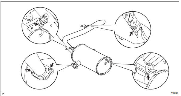
(c) Remove the gasket from the center exhaust pipe assembly.
4. REMOVE CENTER EXHAUST PIPE ASSEMBLY
(a) Remove the 2 bolts and 2 compression springs.
(b) Disconnect the 2 exhaust pipe supports and remove the center exhaust pipe assembly
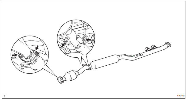
(c) Remove the gasket from the front exhaust pipe assembly.
5. REMOVE FRONT EXHAUST PIPE ASSEMBLY
(a) Disconnect the heated oxygen sensor (for bank 2 sensor 2) connector.
(b) Remove the 6 nuts and front exhaust pipe assembly.
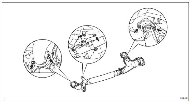
(c) Remove the 2 gaskets from the front exhaust pipe assembly.
6. REMOVE NO. 1 EXHAUST PIPE SUPPORT BRACKET
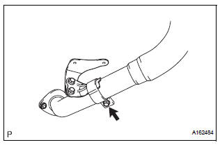
(a) Remove the bolt and No. 1 exhaust pipe support bracket.
7. REMOVE HEATED OXYGEN SENSOR (for Bank 2 Sensor 2) (See page EC-33)
 Exhaust pipe (for 2wd)
Components
...
 Installation
1. Install heated oxygen sensor (for bank 2
sensor 2) (see page ec-34)
2. Install front exhaust pipe assembly
(a) Install 2 new gaskets to the front exhaust pipe
assembly.
(b) Install the front ...
Other materials:
Trouble in Passenger Airbag ON / OFF Indicator
DESCRIPTION
The occupant classification system detects the front passenger seat
condition. It then informs a
passenger of the front passenger airbag, the front seat side airbag RH and front
seat belt pretensioner
RH condition (activated/not activated) by the passenger airbag ON/OFF indicator. ...
Sleep Operation Failure of Occupant Classification
ECU
DTC B1796 Sleep Operation Failure of Occupant Classification
ECU
DESCRIPTION
During sleep mode, the occupant classification ECU reads the condition of
each sensor while the ignition
switch is off.
In this mode, if the occupant classification ECU detects an internal
malfunction, DTC B1796 ...
Installation
1. INSTALL BRAKE VACUUM CHECK VALVE
ASSEMBLY
(a) Install the brake vacuum check valve assembly and
check valve grommet to the brake booster
assembly.
2. INSTALL BRAKE BOOSTER GASKET
(a) Install a new brake booster gasket to the brake
booster with master cylinder.
3. INSTALL BRAKE MASTER CYLI ...
