Toyota Sienna Service Manual: Installation
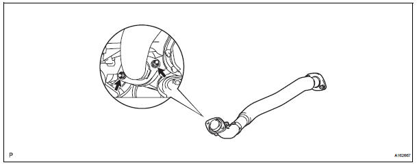
1. INSTALL HEATED OXYGEN SENSOR (for Bank 2 Sensor 2) (See page EC-39) 2. INSTALL FRONT EXHAUST PIPE ASSEMBLY
(a) Install a new gasket to the front exhaust pipe assembly.
(b) Install the front exhaust pipe assembly with the 2 nuts.
Torque: 62 N*m (632 kgf*cm, 46 ft.*lbf)
3. V
V(A) install 2 new gaskets to the center exhaust pipe assembly.
(B) connect the 2 exhaust pipe supports, and install the center exhaust pipe assembly.
(C) install 2 new bolts and 2 nuts.
Torque: bolt 43 n*m (438 kgf*cm, 32 ft.*Lbf) nut 62 n*m (632 kgf*cm, 46 ft.*Lbf)
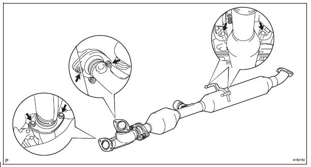
4. Install no. 1 Exhaust pipe support bracket
(a) Install the No. 1 exhaust pipe support bracket to oil pan sub-assembly with 2 new nuts.
Torque: 21 N*m (214 kgf*cm, 15 ft.*lbf) (b) Loosen the No. 1 exhaust pipe support bracket bolts.
(c) Install the clamp to No. 1 exhaust pipe support bracket.
(d) Retighten the No. 1 exhaust pipe support bracket bolts.
Torque: 21 N*m (214 kgf*cm, 15 ft.*lbf) (e) Install the clamp with a new bolt.
Torque: 21 N*m (214 kgf*cm, 15 ft.*lbf)
(f) Connect the heated oxygen sensor (for bank 2 sensor 2) connector.
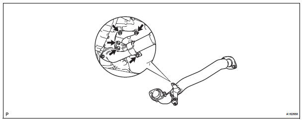
5. INSTALL TAIL EXHAUST PIPE ASSEMBLY
(a) Install a new gasket to the center exhaust pipe assembly.
(b) Connect the 4 exhaust pipe supports, and install the tail exhaust pipe assembly.
(c) Install 2 new bolts.
Torque: 43 N*m (438 kgf*cm, 32 ft.*lbf)
6. INSTALL HEATED OXYGEN SENSOR (for Bank 1 Sensor 2) (See page EC-41)
7. CONNECT CABLE TO NEGATIVE BATTERY TERMINAL
8. INSPECT FOR EXHAUST GAS LEAK
If exhaust gas is leaking, repair the leak. Replace damaged parts as necessary.
 Removal
1. DISCONNECT CABLE FROM NEGATIVE BATTERY
TERMINAL
2. REMOVE HEATED OXYGEN SENSOR (for Bank 1
Sensor 2) (See page EC-38)
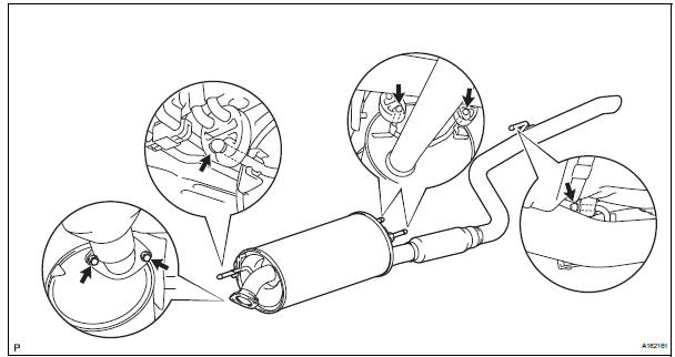
3. REMOVE TAIL EXHAUST PIPE ASSEMBLY
(a) Remove the 2 bolts.
(b) Discon ...
 2Gr-fe cooling
...
Other materials:
A/C ECU Communication Stop
DTC B1262 A/C ECU Communication Stop
DESCRIPTION
DTC B1262 is output when communication between the A/C amplifier and the
multiplex network gateway
ECU stops for more than 10 seconds.
DTC No.
DTC Detection Condition
Trouble Area
B1262
A/C ECU communicat ...
Releasing and stowing the seat belt (for the third center seat)
To release plate “B”, press the
release button on buckle “B”.
To release plate “A”, insert the
key or plate “B” into
the hole on buckle “A”.
Retract the belt slowly when
releasing and stowing the seat
belt.
Insert the seat belt plates into
...
Removal
1. DRAIN BRAKE FLUID
NOTICE:
Wash brake fluid off immediately if it adheres to any
painted surface.
2. DISCONNECT BATTERY NEGATIVE TERMINAL
3. REMOVE AIR CLEANER ASSEMBLY WITH HOSE
4. REMOVE BRAKE ACTUATOR WITH BRACKET
(a) Release the latch of the brake actuator connector to
disconnect t ...
