Toyota Sienna Service Manual: Removal
1. DISCONNECT CABLE FROM NEGATIVE BATTERY TERMINAL
2. REMOVE HEATED OXYGEN SENSOR (for Bank 1 Sensor 2) (See page EC-38)
3. REMOVE TAIL EXHAUST PIPE ASSEMBLY
(a) Remove the 2 bolts.
(b) Disconnect the 4 exhaust pipe supports and remove the tail exhaust pipe assembly.
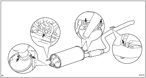
(c) Remove the gasket from the center exhaust pipe assembly.
4. REMOVE CENTER EXHAUST PIPE ASSEMBLY
(a) Remove the 2 bolts and 2 nuts.
(b) Disconnect the 2 exhaust pipe supports and remove the center exhaust pipe assembly.
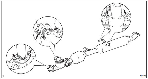
(c) Remove the gaskets from the center exhaust pipe assembly and the front exhaust pipe assembly.
5. REMOVE FRONT EXHAUST PIPE ASSEMBLY
(a) Disconnect the heated oxygen sensor (for bank 2 sensor 2) connector.
(b) Remove the 4 nuts and front exhaust pipe assembly.
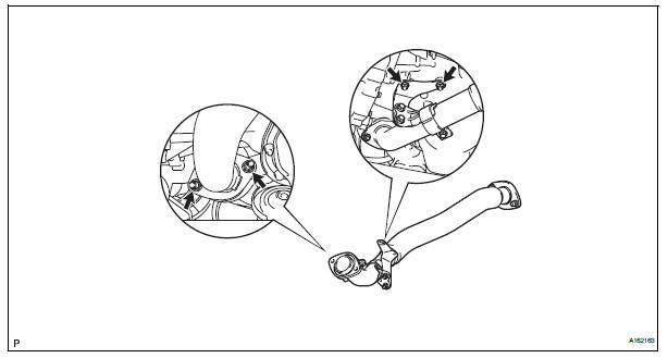
(c) Remove the gasket from the front exhaust pipe assembly.
6. REMOVE NO. 1 EXHAUST PIPE SUPPORT BRACKET
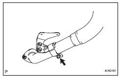
(a) Remove the bolt and No. 1 exhaust pipe support bracket.
7. REMOVE HEATED OXYGEN SENSOR (for Bank 2 Sensor 2) (See page EC-38)
 Exhaust pipe (for 4wd)
Components
...
 Installation
1. INSTALL HEATED OXYGEN SENSOR (for Bank 2
Sensor 2) (See page EC-39)
2. INSTALL FRONT EXHAUST PIPE ASSEMBLY
(a) Install a new gasket to the front exhaust pipe
assembly.
(b) Install the front ...
Other materials:
Basic inspection
When a malfunction is not confirmed by the DTC check,
troubleshooting should be carried out in all circuits
considered to be possible causes of the problem. In many
cases, by carrying out the basic engine check shown in the
following flowchart, the location of the problem can be found
quickly a ...
Throttle Actuator Control System
DTC P2111 Throttle Actuator Control System - Stuck Open
DTC P2112 Throttle Actuator Control System - Stuck
Closed
DESCRIPTION
The throttle actuator is operated by the ECM, and opens and closes the
throttle valve using the gears.
The opening angle of the throttle valve is detected by the Thr ...
Open in Curtain Shield Squib RH Circuit
DTC B1161/84 Open in Curtain Shield Squib RH Circuit
DESCRIPTION
The curtain shield squib RH circuit consists of the center airbag sensor
assembly and the curtain shield
airbag assembly RH.
The circuit instructs the SRS to deploy when deployment conditions are met.
DTC B1161/84 is recorde ...
