Toyota Sienna Service Manual: Installation
1. INSTALL WATER PUMP ASSEMBLY
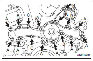
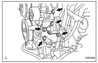
(a) Install a new water pump gasket and the water pump assembly with the 16 bolts.
Torque: Bolt A 21 N*m (214 kgf*cm, 15 ft.*lbf) Bolts B and C 9.1 N*m (93 kgf*cm, 81 in.*lbf)
NOTICE:
|
2. INSTALL WATER INLET HOUSING
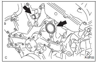
(a) Install a new water inlet housing No. 1 gasket and water outlet pipe O-ring.
(b) Install the water inlet housing with the 2 bolts and nut.
Torque: 10 N*m (102 kgf*cm, 7 ft.*lbf)
| NOTICE: Be careful not to allow the O-ring to get caught between the parts. |
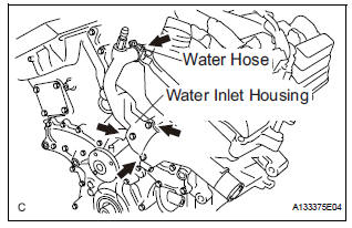
(c) Connect the water hose.
3. INSTALL WATER PUMP PULLEY
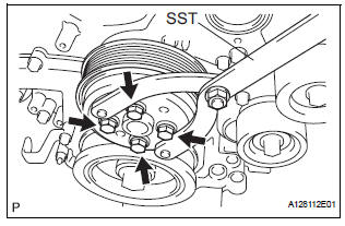
(a) Temporarily install the water pump pulley with the 4 bolts.
(b) Using SST, hold the water pump pulley.
SST 09960-10010 (09962-01000, 09963-00700) (c) Tighten the 4 bolts.
Torque: 21 N*m (214 kgf*cm, 15 ft.*lbf)
4. INSTALL V-RIBBED BELT TENSIONER ASSEMBLY
(a) Install the V-ribbed belt tensioner assembly with the 5 bolts.
Torque: 43 N*m (438 kgf*cm, 32 ft.*lbf)
5. INSTALL NO. 2 IDLER PULLEY SUB-ASSEMBLY
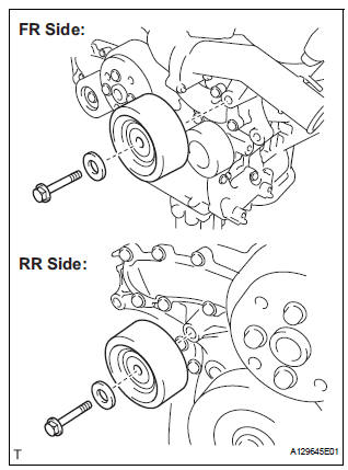
(a) Install the 2 idler pulley cover plates and idler pulley sub-assemblies with the 2 bolts.
Torque: 43 N*m (438 kgf*cm, 32 ft.*lbf)
6. INSTALL NO. 1 ENGINE FRONT MOUNTING BRACKET LH (See page EM-45) 7. INSTALL GENERATOR ASSEMBLY (See page CH-26) 8. INSTALL COMPRESSOR AND MAGNETIC CLUTCH (See page AC-231) 9. INSTALL ENGINE HANGERS (See page EM-50) 10. REMOVE ENGINE STAND 11. INSTALL ENGINE ASSEMBLY WITH TRANSAXLE HINT: See page EM-44 12. ADD ENGINE COOLANT (See page CO-7) 13. INSPECT FOR COOLANT LEAK (See page CO-1)
 Inspection
1. Inspect water pump assembly
(a) Visually check the drain hole and air hole for coolant
leakage.
(b) Turn the pulley, and check that the water pump
bearing moves smoothly and noiselessly.
...
 Thermostat
Components
...
Other materials:
Display contents
The multi-information display presents
the driver with a variety of
vehicle data.
Menu icons
Displays the following information when an icon is selected.
Some of the information may be displayed automatically depending
on the situation.
Drive information
Select to display various ...
Power Seat ECU Communication Stop
DTC B1272 Power Seat ECU Communication Stop
DESCRIPTION
This DTC is detected when communication between the seat position control ECU
and the multiplex
network gateway ECU stops for more than 10 seconds.
DTC No.
DTC Detection Condition
Trouble Area
B1272
...
Inspection
1. INSPECT TIRES
(a) Check the tires for wear and proper inflation
pressure.
Cold tire inflation pressure
(b) Using a dial indicator, check the runout of the tires.
Tire runout:
1.4 mm (0.055 in.) or less
2. ROTATE TIRES
HINT:
Rotate the tires as shown in the illustration.
3. INSP ...
