Toyota Sienna Service Manual: TC and CG Terminal Circuit
DESCRIPTION
Connecting terminals TC and CG of the DLC3 causes the system to enter the self-diagnostic mode. If a malfunction is present, DTCs will be output.
HINT: When a particular warning light remains blinking, a ground short in the wiring of terminal TC of the DLC3 or an internal ground short in the relevant ECU is suspected.
WIRING DIAGRAM
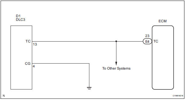
INSPECTION PROCEDURE
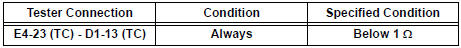
1 CHECK HARNESS AND CONNECTOR (TERMINAL TC of DLC3 - ECM)

- Disconnect the E4 connector from the ECM.
- Measure the resistance according to the value(s) in the table below.
Standard resistance
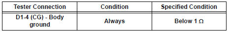
2 CHECK HARNESS AND CONNECTOR (TERMINAL CG of DLC3 - BODY GROUND)
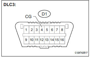
- Measure the resistance according to the value(s) in the table below.
Standard resistance
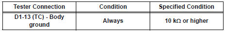
3 CHECK HARNESS AND CONNECTOR (TERMINAL TC of DLC3 - BODY GROUND)
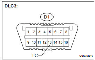
- Measure the resistance according to the value(s) in the table below.
Standard resistance
PROCEED TO NEXT CIRCUIT INSPECTION SHOWN IN PROBLEM SYMPTOMS TABLE
 Cruise Main Indicator Light Circuit
DESCRIPTION
When the cruise control main switch is on, the CRUISE main indicator light
and READY indicator light
come on. This indicates the control condition (presence or absence of a vehicle
i ...
 Cruise control main switch
COMPONENTS
Removal
1. DISCONNECT BATTERY NEGATIVE TERMINAL
2. REMOVE STEERING WHEEL COVER LOWER NO.2
(24)
3. REMOVE STEERING WHEEL COVER LOWER NO.3
(24)
4. REMOVE HORN BUTTON ASSEMBLY
...
Other materials:
Removal
1. PRECAUTION
CAUTION:
Be sure to read "PRECAUTION" thoroughly before servicing.
2. DISCONNECT CABLE FROM NEGATIVE BATTERY
TERMINAL
CAUTION:
Wait for 90 seconds after disconnecting the cable to
prevent the airbag working.
3. REMOVE FRONT SEAT ASSEMBLY (for Manual Seat)
4. REMOVE F ...
Turn signal lever
Operating instructions
Right turn
Left turn
Lane change to the right (move
the lever partway and release
it)
The right hand signals will flash 3
times.
Lane change to the left (move
the lever partway and release
it)
The left hand signals will flash 3
times.
Turn sign ...
Safety information for Safety Connect
Important! Read this information before using Safety Connect.
Exposure to radio frequency signals
The Safety Connect system installed in your vehicle is a low-power
radio transmitter and receiver. It receives and also sends out radio
frequency (RF) signals.
In August 1996, the Federal Communi ...
