Toyota Sienna Service Manual: Manual Up / Down Function does not Operate on Rear LH Only
DESCRIPTION
If the manual UP/DOWN function does not operate, the power window motor, the regulator switch or the wire harness may be malfunctioning.
WIRING DIAGRAM
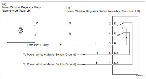
INSPECTION PROCEDURE
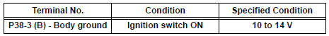
1 CHECK WIRE HARNESS (POWER SOURCE)
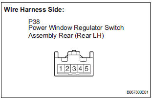
- Disconnect the P38 regulator switch connector.
- Turn the ignition switch ON.
- Check the voltage between the terminal 4 of the wire harness side connector and the body ground.
Standard voltage
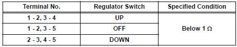
2 INSPECT POWER WINDOW REGULATOR SWITCH (REAR LH)
- Remove the regulator switch.
- Check the resistance between the switch terminals when the switch is operated, as shown in the table below.
Standard resistance
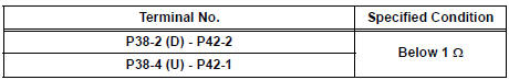
3 CHECK WIRE HARNESS (REGULATOR SWITCH - MOTOR) (REGULATOR SWITCH - BODY GROUND)
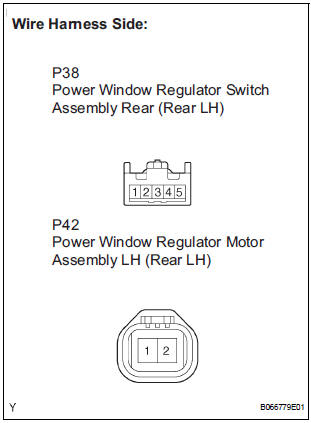
- Disconnect the P42 motor connector.
- Check the resistance between the wire harness side connectors.
Standard resistance
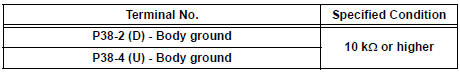
- Check the resistance between the P38 regulator switch connector and body ground.
Standard resistance
4 INSPECT POWER WINDOW REGULATOR MOTOR ASSEMBLY (REAR LH)
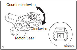
- Remove the motor.
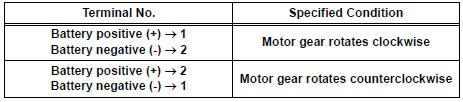
- Apply battery voltage to connector terminals 1 and 2.
- Check that the motor smoothly rotates.
NOTICE: Do not apply battery voltage to any terminals except terminals 1 and 2.
Standard
REPAIR OR REPLACE HARNESS AND CONNECTOR (MASTER SWITCH - REGULATOR SWITCH)
 Manual Up / Down and Auto Down Function does not Operate on
Passenger Side Only
Manual Up / Down and Auto Down Function does not Operate on
Passenger Side Only
DESCRIPTION
If the manual UP/DOWN function does not operate, the power window motor, the
regulator switch or the
wire harness may be malfunctioning.
WIRING DIAGRAM
INSPECTION PROCEDURE
1 CH ...
 Manual Up / Down Function does not Operate on Rear RH Only
DESCRIPTION
If the manual UP/DOWN function does not operate, the power window motor, the
regulator switch or the
wire harness may be malfunctioning.
WIRING DIAGRAM
INSPECTION PROCEDURE
1 CH ...
Other materials:
Repair
1. INSTALL HEADLIGHT PROTECTOR RETAINER UPPER
HINT:
If the installation area of the headlight assembly is
damaged, use the supply bracket for low-cost repair.
Ensure that the headlight assembly is not damaged.
Cut off the part shaded in the illustration and sand
smoo ...
DSP Error
DTC 63-78 DSP Error
DESCRIPTION
DTC No.
DTC Detection Condition
Trouble Area
63-78
An error occurs during the decode process (MP3 /
WMA).
-
INSPECTION PROCEDURE
HINT:
After the inspection completed, clear the DTCs.
NOTICE:
This ...
Manual Up / Down Function does not Operate on Rear RH Only
DESCRIPTION
If the manual UP/DOWN function does not operate, the power window motor, the
regulator switch or the
wire harness may be malfunctioning.
WIRING DIAGRAM
INSPECTION PROCEDURE
1 CHECK WIRE HARNESS (POWER SOURCE)
Disconnect the P39 regulator switch connector.
Turn ...
