Toyota Sienna Service Manual: Manual Up / Down and Auto Down Function does not Operate on Driver Side
DESCRIPTION
If the manual UP/DOWN function does not operate, no power may be supplied to the power window master switch or the power window motor. The power window master switch itself or the wire harness may be malfunctioning.
WIRING DIAGRAM
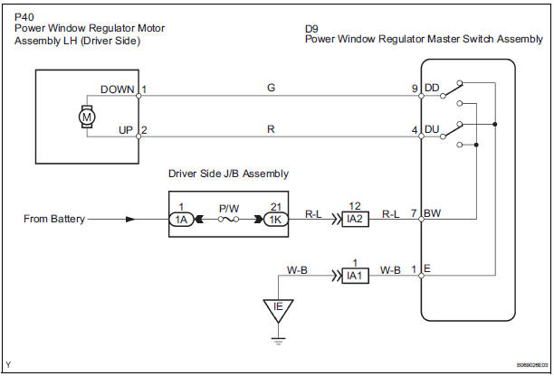
INSPECTION PROCEDURE
1 INSPECT FUSE (P/W)
- Remove the fuse from the driver side J/B.
- Check the resistance.
Standard resistance: Below 1 Ω
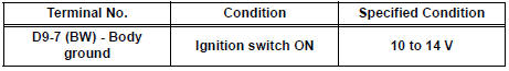
2 CHECK WIRE HARNESS (TERMINAL BW)
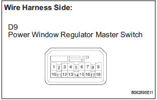
- Turn the ignition switch ON.
- Check the voltage between the terminal of the wire harness side connector and the body ground.
Standard voltage
3 INSPECT POWER WINDOW MASTER SWITCH
- Remove the master switch.
- Check the resistance between the terminals of the master switch when the AUTO (driver side) switch is operated, as shown in the table below.
Standard resistance

4 CHECK WIRE HARNESS (MASTER SWITCH - MOTOR) (MASTER SWITCH - BODY GROUND))
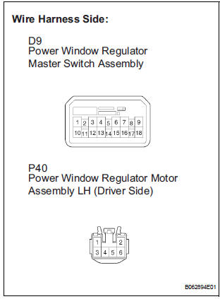
- Disconnect the D9 master switch connector.
- Disconnect the P40 motor connector.
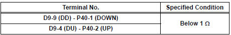
- Check the resistance between the wire harness side connectors.
Standard resistance
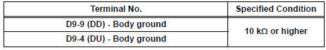
- Check the resistance between the D9 master switch connector and body ground.
Standard resistance
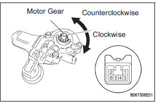
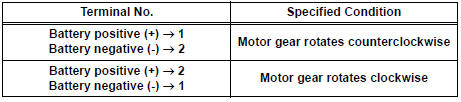
- Reference: Check operation of the power window motor (driver side).
- Remove the motor.
- Apply battery voltage to connector terminals 1 and 2.
- Check that the motor smoothly rotates.
NOTICE: Do not apply battery voltage to any terminals except terminals 1 and 2.
Standard
REPLACE POWER WINDOW REGULATOR MOTOR ASSEMBLY (DRIVER SIDE)
 Remote Up / Down Function does not Operate
DESCRIPTION
If the REMOTE UP/DOWN function does not operate, any of the following
troubles may be the cause:
There is an open or short circuit in the wiring between the power
window ma ...
 Manual Up / Down and Auto Down Function does not Operate on
Passenger Side Only
Manual Up / Down and Auto Down Function does not Operate on
Passenger Side Only
DESCRIPTION
If the manual UP/DOWN function does not operate, the power window motor, the
regulator switch or the
wire harness may be malfunctioning.
WIRING DIAGRAM
INSPECTION PROCEDURE
1 CH ...
Other materials:
Disassembly
1. REMOVE REAR DIFFERENTIAL CARRIER COVER
(a) Remove the 8 bolts from the carrier cover.
(b) Using a brass bar and a hammer, separate the
carrier cover from rear differential carrier assembly.
(c) Remove the breather plug from the rear differential
carrier cover.
(d) Remove the bol ...
Disassembly
1. REMOVE GENERATOR CLUTCH PULLEY
(A) using a screwdriver, remove the generator pulley
cap.
(b) Set SST (A) and (B).
SST 09820-63020
(c) Clamp SST (A) in a vise.
NOTICE:
Be sure to fix the flat surface of SST (A) in a
vise.
(d) Place the rotor shaft end int ...
VIN not Programmed or Mismatch - ECM / PCM
DESCRIPTION
DTC P0630 is set when the Vehicle Identification Number (VIN) is not stored
in the Engine Control Module
(ECM) or the input VIN is not accurate. Input the VIN with the intelligent
tester.
MONITOR STRATEGY
TYPICAL ENABLING CONDITIONS
TYPICAL MALFUNCTION THRESHOLDS ...
