Toyota Sienna Service Manual: Position Sensor Circuit
DESCRIPTION
When SET and 1 or 2 are pressed, the position sensor detects the mirror position and sends the signal to the outer mirror control ECU. Then when position 1 or 2 is pressed, the outer mirror control ECU drives the mirror motor based on the memorized sensor positions.
HINT: The power mirror control system is part of the multiplex communication system. This system features shared communication wiring that reduces the wiring complexity of the communication lines. The first step in any repair is to confirm the proper operation of the communication system. Proceed with troubleshooting after the communication has been verified (See Multiplex Communication System)
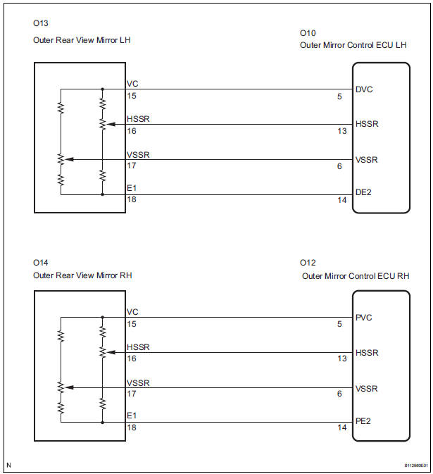
WIRING DIAGRAM
INSPECTION PROCEDURE
1 READ VALUE OF INTELLIGENT TESTER
- Connect the intelligent tester to the DLC3.
- Ignition switch on.
- Enter the following menus: DIAGNOSIS / ENHANCED OBD II / DATA LIST.
- Read the DATA LIST according to the display on the tester.
MIRROR-L/MIRROR-R

OK: Tester displayed is 0 V to 5 V.
2 CHECK HARNESS AND CONNECTOR (OUTER REAR VIEW MIRROR - OUTER MIRROR CONTROL ECU)
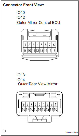
- Disconnect the O10 or O12 ECU connector.
- Disconnect the O13 or O14 outer mirror connector.
- Measure the resistance according to the value(s) in the table below.
Resistance
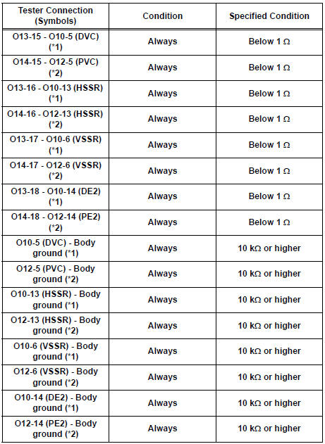
*1: LH side
*2: RH side
REPLACE OUTER MIRROR CONTROL ECU
 Mirror Motor Circuit
DESCRIPTION
A mirror control switch signal and memorized mirror positions are sent to the
outer mirror control ECU.
The outer mirror control ECU drives the selected mirror UP, DOWN, LEFT and RIG ...
 Memory Switch Circuit
DESCRIPTION
When the seat memory switch M1 or M2 is pressed, the position control ECU &
switch (Seat ECU)
transmits a signal of the memorized mirror position to the outer mirror control
ECU. ...
Other materials:
Sound Signal Circuit between Radio Receiver and Television Display
Assembly
DESCRIPTION
The television display assembly sends a sound signal to the radio receiver
through this circuit.
The sound signal that has been sent is amplified by the stereo component
amplifier or radio receiver
(built-in amplifier), and then is sent to the speakers.
If there is an open or ...
Removal
1. RECOVER REFRIGERANT FROM REFRIGERATION
SYSTEM (See page AC-172)
2. REMOVE FRONT WHEEL RH
3. REMOVE FRONT FENDER APRON SEAL RH (See
page EM-26)
4. REMOVE V-RIBBED BELT (See page EM-6)
5. REMOVE RADIATOR AND FAN ASSEMBLY
(See page CO-28)
6. DISCONNECT DISCHARGE HOSE SUB-ASSEMBLY
(a) Re ...
System description
1. GENERAL
The dynamic laser cruise control system has two
cruise control modes: the constant speed control
mode and vehicle-to-vehicle distance control mode.
The vehicle-to-vehicle distance control mode is
always selected when starting the dynamic laser
cruise control ...
