Toyota Sienna Service Manual: No. 2 Ultrasonic sensor
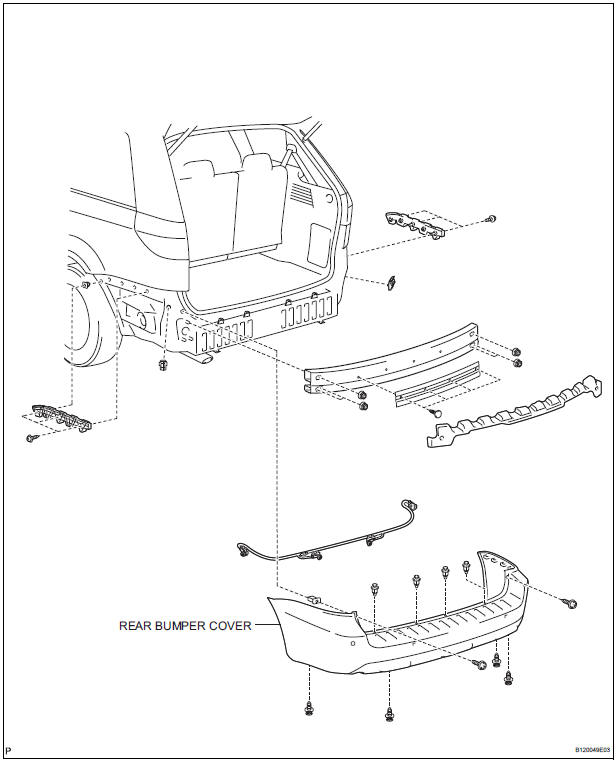
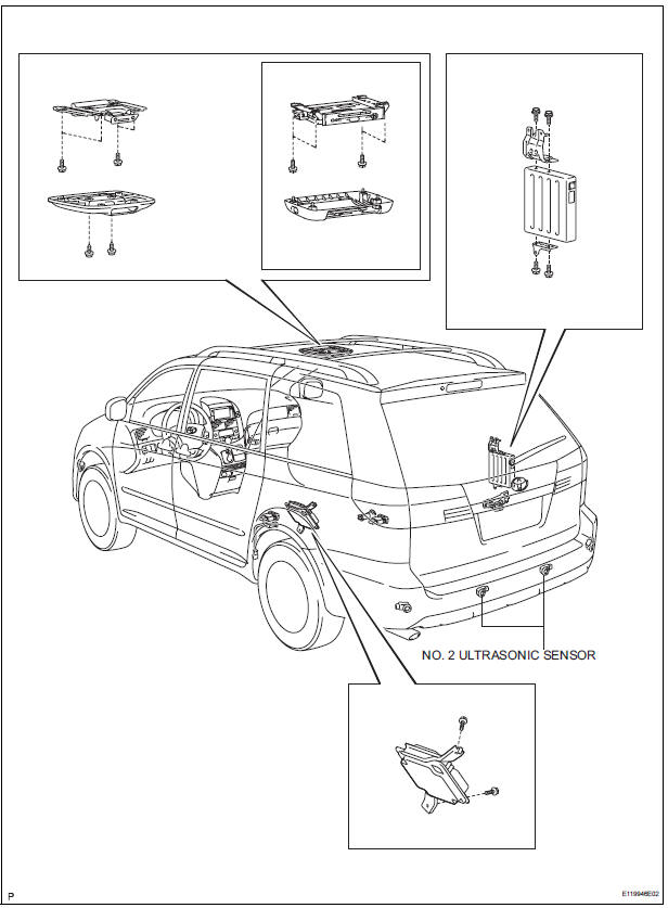
COMPONENTS
REMOVAL
1. REMOVE REAR BUMPER COVER (2)
2. REMOVE NO. 1 ULTRASONIC SENSOR RETAINER
- Remove the No. 1 ultrasonic sensor retainer as shown in the illustration
3. REMOVE NO. 2 ULTRASONIC SENSOR
- Disconnect the connector and remove the No. 2 ultrasonic sensor
INSPECTION
1. INSPECT NO.2 ULTRASONIC SENSOR
- Measure the resistance according to the value(s) in the table below.
Standard resistance
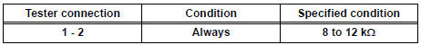
If the result is not as specified, replace No.2 ultrasonic sensor
INSTALLATION
1. INSTALL NO. 2 ULTRASONIC SENSOR
- Connect the connector and install the No. 2 ultrasonic sensor.
2. INSTALL NO. 1 ULTRASONIC SENSOR RETAINER
- Install the No. 1 ultrasonic sensor retainer.
3. INSTALL REAR BUMPER COVER
 No. 1 Ultrasonic sensor
COMPONENTS
REMOVAL
1. REMOVE FRONT FENDER LINER LH
2. REMOVE FRONT FENDER LINER RH
3. REMOVE FRONT BUMPER COVER
4. REMOVE REAR BUMPER COVER (2)
5. REMOVE NO. 1 ULTRASONIC SENSOR RETAINER
...
 Television camera
COMPONENTS
REMOVAL
1. REMOVE BACK DOOR GARNISH CENTER
HINT:
Back Door:
Power Back Door:
2. REMOVE BACK DOOR SIDE GARNISH LH
HINT:
Back Door:
Pow ...
Other materials:
Locking the front doors from the outside without a key
Move the inside lock button to the lock position.
Close the door.
Vehicles without a smart key system
The doors cannot be locked if either of the front doors is open and the
key is in the engine switch.
Vehicles with a smart key system
The door cannot be locked if the engine switc ...
Installation
1. INSTALL YAW RATE AND DECELERATION SENSOR
(a) Connect the yawrate sensor connector.
(b) Install the yawrate sensor with the 2 bolts.
Torque: 13 N*m (136 kgf*cm, 10 ft.*lbf)
2. INSTALL COWL SIDE TRIM BOARD RH
(a) Install the nut with the cowl side trim board plate
RH.
3. INSTALL FRONT ...
Third outside seats
To use
Pull the head restraints up.
To fold
Press the button
Removing the head restraints
Front and second outside seats
Pull the head restraint up while pressing
the lock release button.
Second center* and third center seats
Pull the head restraint up while pressi ...
