Toyota Sienna Service Manual: Television camera
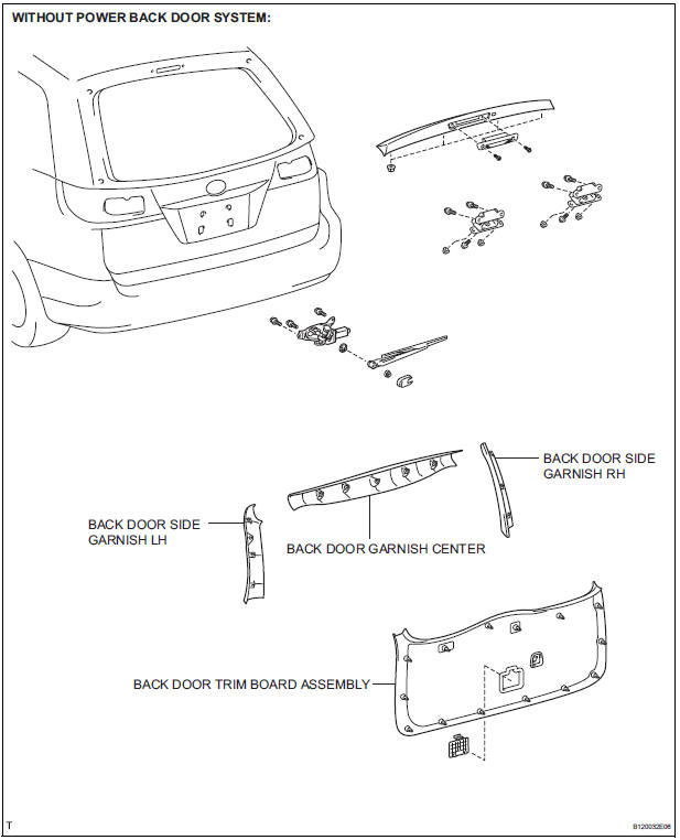
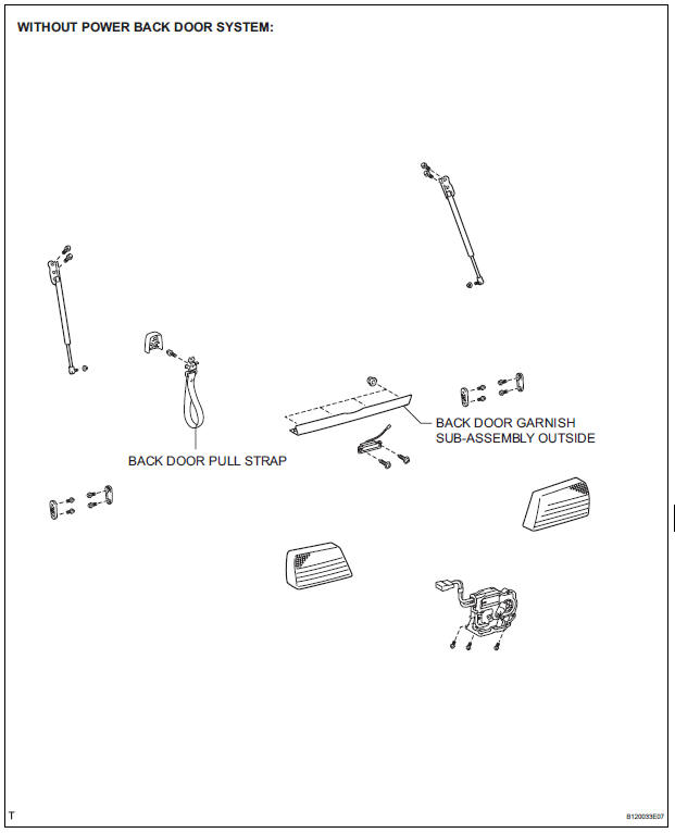
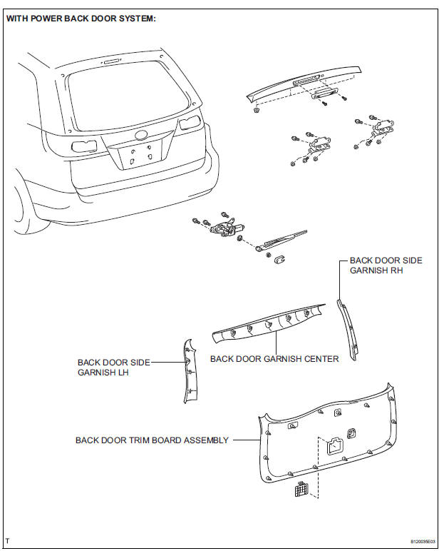
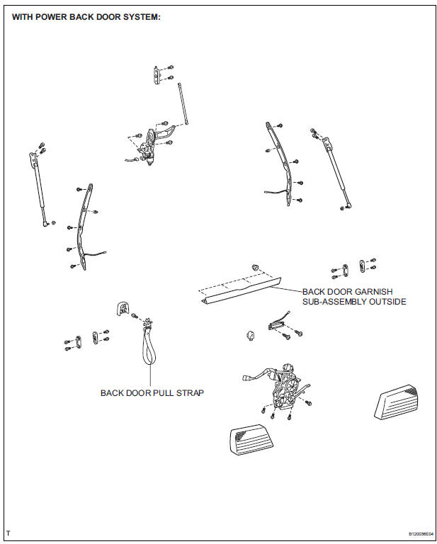
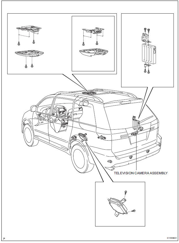
COMPONENTS
REMOVAL
1. REMOVE BACK DOOR GARNISH CENTER
HINT:
- Back Door:
- Power Back Door:
2. REMOVE BACK DOOR SIDE GARNISH LH
HINT:
- Back Door:
- Power Back Door:
3. REMOVE BACK DOOR SIDE GARNISH RH
- Back Door:
- Power Back Door:
4. REMOVE BACK DOOR PULL STRAP
- Back Door:
- Power Back Door:
5. REMOVE BACK DOOR TRIM BOARD ASSEMBLY
- Back Door:
- Power Back Door:
6. REMOVE BACK DOOR GARNISH SUB-ASSEMBLY OUTSIDE
- Back Door:
- Power Back Door:
7. REMOVE TELEVISION CAMERA ASSEMBLY
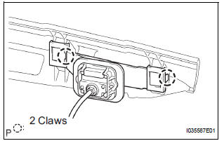
- Release the 2 claw fittings and remove the television camera assembly.
INSTALLATION
1. INSTALL TELEVISION CAMERA ASSEMBLY
2. INSTALL BACK DOOR GARNISH SUB-ASSEMBLY OUTSIDE
3. INSTALL BACK DOOR TRIM BOARD ASSEMBLY
4. INSTALL BACK DOOR PULL STRAP
HINT:
- Back Door:
- Power Back Door:
5. INSTALL BACK DOOR SIDE GARNISH RH
6. INSTALL BACK DOOR SIDE GARNISH LH
7. INSTALL BACK DOOR GARNISH CENTER
 No. 2 Ultrasonic sensor
COMPONENTS
REMOVAL
1. REMOVE REAR BUMPER COVER (2)
2. REMOVE NO. 1 ULTRASONIC SENSOR RETAINER
Remove the No. 1 ultrasonic sensor retainer as
shown in the illustration
3. REMO ...

Other materials:
Bottle holders
Front
Rear
When storing a bottle, close the cap.
The bottle may not be stored depending on its size or shape.
WARNING
Do not place anything other than a bottle in the bottle holders.
Other items may be thrown out of the holders in the event of an accident
...
When servicing full-time 4wd vehicles
The full-time 4WD SIENNA is equipped with the open
center differential system.
If incorrect preparations or test procedures are used, the
test will not only be unsuccessful, but may be dangerous
as well.
Therefore, before beginning any such servicing or test,
be sure to check the following ...
Reassembly
1. INSTALL REAR WHEEL CYLINDER CUP KIT
(a) Temporarily tighten the bleeder plug to the wheel
cylinder, and install the bleeder plug cap.
(b) Apply lithium soap base glycol grease to the 2 new
wheel cylinder cups and the 2 pistons.
(c) Install the 2 wheel cylinder cups to each piston.
...
