Toyota Sienna Service Manual: Short to GND in Front Passenger Side Squib 2nd Step Circuit
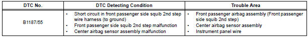
DTC B1187/55 Short to GND in Front Passenger Side Squib 2nd Step Circuit
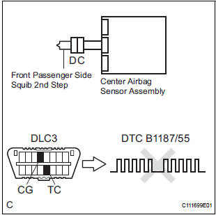
DESCRIPTION
The front passenger side squib 2nd step circuit consists of the center airbag sensor assembly and the front passenger airbag assembly.
The circuit instructs the SRS to deploy when deployment conditions are met.
DTC B1187/55 is recorded when a short to ground is detected in the front passenger side squib 2nd step circuit.
WIRING DIAGRAM
INSPECTION PROCEDURE
HINT:
- Perform the simulation method by selecting the "check mode" (signal check) with the intelligent tester.
- After selecting the "check mode" (signal check), perform the simulation method by wiggling each connector of the airbag system or driving the vehicle on a city or rough road
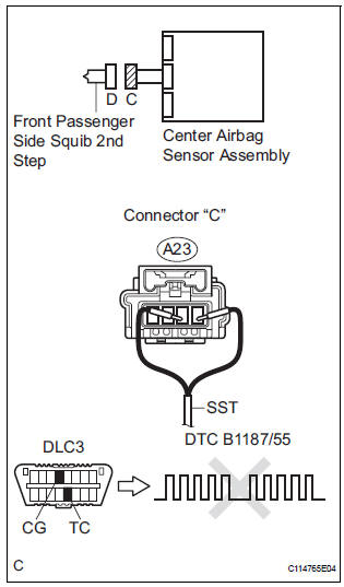
1 CHECK FRONT PASSENGER AIRBAG ASSEMBLY (FRONT PASSENGER SIDE SQUIB 2ND STEP)
- Turn the ignition switch to the LOCK position.
- Disconnect the negative (-) terminal cable from the battery, and wait for at least 90 seconds.
- Disconnect the connectors from the front passenger airbag assembly.
- Connect the black wire side of SST (resistance 2.1 Ω) to
the instrument panel wire.
CAUTION: Never connect a tester to the front passenger airbag assembly (front passenger side squib 2nd step) for measurement, as this may lead to a serious injury due to airbag deployment.
NOTICE: Do not forcibly insert the SST into the terminals of the connector when connecting.
Insert the SST straight into the terminals of the connector.
SST 09843-18060
- Connect the negative (-) terminal cable to the battery, and wait for at least 2 seconds.
- Turn the ignition switch to the ON position, and wait for at least 60 seconds.
- Clear the DTCs stored in memory.
- Turn the ignition switch to the LOCK position.
- Turn the ignition switch to the ON position, and wait for at least 60 seconds.
- Check the DTCs.
OK: DTC B1187/55 is not output.
HINT: Codes other than DTC B1187/55 may be output at this time, but they are not related to this check.
REPLACE FRONT PASSENGER AIRBAG ASSEMBLY
2 CHECK INSTRUMENT PANEL WIRE (FRONT PASSENGER SIDE SQUIB 2ND STEP CIRCUIT)
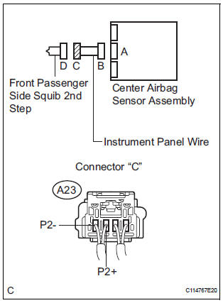
- Turn the ignition switch to the LOCK position.
- Disconnect the negative (-) terminal cable from the battery, and wait for at least 90 seconds.
- Disconnect the SST (resistance 2.1 Ω) from the instrument panel wire.
- Disconnect the connector from the center airbag sensor assembly.
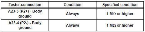
- Measure the resistance according to the value(s) in the table below.
Standard resistance
3 CHECK CENTER AIRBAG SENSOR ASSEMBLY
- Connect the connectors to the front passenger airbag assembly and the center airbag sensor assembly.
- Connect the negative (-) terminal cable to the battery, and wait for at least 2 seconds.
- Turn the ignition switch to the ON position, and wait for at least 60 seconds.
- Clear the DTCs stored in memory.
- Turn the ignition switch to the LOCK position.
- Turn the ignition switch to the ON position, and wait for at least 60 seconds.
- Check the DTCs.
OK: DTC B1187/55 is not output.
HINT: Codes other than DTC B1187/55 may be output at this time, but they are not related to this check.
USE SIMULATION METHOD TO CHECK
 Open in Front Passenger Side Squib 2nd Step
Circuit
Open in Front Passenger Side Squib 2nd Step
Circuit
DTC B1186/58 Open in Front Passenger Side Squib 2nd Step
Circuit
DESCRIPTION
The front passenger side squib 2nd step circuit consists of the center airbag
sensor assembly and the
front passenger ...
 Short to B+ in Front Passenger Side Squib 2nd
Step Circuit
Short to B+ in Front Passenger Side Squib 2nd
Step Circuit
DTC B1188/56 Short to B+ in Front Passenger Side Squib 2nd
Step Circuit
DESCRIPTION
The front passenger side squib 2nd step circuit consists of the center airbag
sensor assembly and the
front pa ...
Other materials:
Transfer
SERVICE DATA
TORQUE SPECIFICATIONS
PROPELLER SHAFT
SERVICE DATA
TORQUE SPECIFICATIONS
DRIVE SHAFT
SERVICE DATA
TORQUE SPECIFICATIONS
DIFFERENTIAL
SERVICE DATA
TORQUE SPECIFICATIONS
AXLE
SERVICE DATA
TORQUE SPECIFICATIONS
...
How to proceed with
troubleshooting
HINT:
The intelligent tester can be used in steps 2, 3, 4, 6 and 9.
1 VEHICLE BROUGHT TO WORKSHOP
2 CONNECT INTELLIGENT TESTER TO DLC3
HINT:
If the display indicates a communication fault in the tester,
inspect the DLC3.
3 CHECK DTC AND FREEZE FRAME DATA
Check for DTC(s) and freeze frame ...
System description
1. SYSTEM DESCRIPTION
(a) ABS
(Anti-lock Brake System)
The ABS helps prevent wheels from locking when
the brake is applied firmly or when braking on a
slippery surface.
(b) EBD
(Electronic Brake force Distribution)
The EBD control utilizes ABS, realizing proper
brake force distribution betw ...
