Toyota Sienna Service Manual: On-vehicle inspection
1. CONNECT INTELLIGENT TESTER
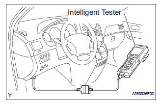
(a) Connect the intelligent tester to the DLC3.
(b) Start the engine and run at idle.
(c) Select the ACTIVE TEST mode on the intelligent tester.
HINT: Please refer to the intelligent tester operator's manual for further details.
2. INSPECT ACTUATOR MOTOR OPERATION
(a) With the motor relay on, check the actuator motor operation noise.
(b) Turn the motor relay off.
(c) Depress the brake pedal and hold it for approximately 15 seconds. Check that the brake pedal cannot be depressed.
(d) With the motor relay on, check that the pedal does not pulsate.
NOTICE: Do not keep the motor relay turned on for more than 5 seconds continuously. When operating it continuously, set an interval of more than 20 seconds.
(e) Turn the motor relay off and release the brake pedal.
3. INSPECT RIGHT FRONT WHEEL OPERATION
NOTICE: Never turn on the solenoids in a manner different to those described below.
(a) With the brake pedal depressed, perform the following operations.
(b) Turn the SFRH and SFRR solenoids on simultaneously, and check that the pedal cannot be depressed.
NOTICE: Do not keep the solenoid turned on for more than 10 seconds continuously. When operating it continuously, set an interval of more than 20 seconds
(c) Turn the SFRH and SFRR solenoids off simultaneously, and check that the pedal can be depressed.
(d) Turn the motor relay on, and check that the pedal returns.
NOTICE: Do not keep the motor relay turned on for more than 5 seconds continuously. When operating it continuously, set an interval of more than 20 seconds.
(e) Turn the motor relay off and release the brake pedal.
4. INSPECT OTHER WHEEL OPERATION
(a) Using the same procedure, check the solenoids of the other wheels.
HINT: Left front wheel: SFLH, SFLR Right rear wheel: SRRH, SRRR Left rear wheel: SRLH, SRLR
 Brake actuator (w/o vsc)
Components
...
 Removal
1. DRAIN BRAKE FLUID
NOTICE:
Wash brake fluid off immediately if it adheres to any
painted surface.
2. DISCONNECT BATTERY NEGATIVE TERMINAL
3. REMOVE AIR CLEANER ASSEMBLY WITH HOSE
4. REMOVE BRA ...
Other materials:
Disassembly
1. REMOVE COOLER DRYER
(a) Using a hexagon wrench 14 mm (0.55 in.), remove
the cap from the modulator.
(b) Remove the O-ring from the cap.
(c) Using needle nose pliers, remove the cooler dryer. ...
Inspection
1. INSPECT FUEL PUMP
(a) Inspect fuel pump resistance.
(1) Using an ohmmeter, measure the resistance
between the terminals.
Standard resistance
(b) Inspect fuel pump operation
(1) Apply battery voltage to both the terminals.
Check that the pump operates.
NOTICE:
These te ...
Initialization
1. RESET
Reset the power slide door system:
The power slide door ECU records the fully open
position of the power slide door in its memory and
the power slide door fully opens and closes based
on this memory. The power slide door cannot
operate without this memory. In the case wh ...
