Toyota Sienna Service Manual: MIL Circuit
DESCRIPTION
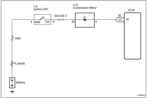
The MIL (Malfunction Indicator Lamp) is used to indicate vehicle malfunctions detected by the ECM.
When the ignition switch is turned to the ON position, power is supplied to the MIL circuit, and the ECM provides the circuit ground which illuminates the MIL.
The MIL operation can be checked visually. When the ignition switch is first turned to the ON position, the MIL should be illuminated and should then turn off. If the MIL remains illuminated or is not illuminated, conduct the following troubleshooting procedure using the intelligent tester.
WIRING DIAGRAM
INSPECTION PROCEDURE
1 CHECK THAT MIL IS ILLUMINATED
(a) Turn the ignition switch to the ON position.
(b) Check the illumination of the MIL.
Result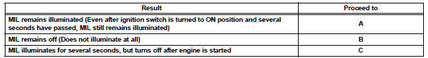

2 CHECK WHETHER MIL TURNS OFF
(a) Connect the intelligent tester to the DLC3.
(b) Turn the ignition switch to the ON position and turn the tester on.
(c) Select the following menu items: DIAGNOSIS / ENHANCED OBD II / DTC INFO / CURRENT CODES.
(d) Check if any DTCs have been stored. Note down any DTCs.
(e) Clear the DTCs (See page ES-39).
(f) Check if the MIL goes off.
Standard: MIL goes off.

3 CHECK HARNESS AND CONNECTOR (CHECK FOR SHORT IN WIRE HARNESS)
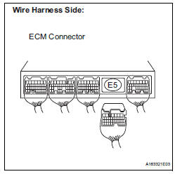
(a) Disconnect the E5 ECM connector.
(b) Turn the ignition switch to the ON position.
(c) Check that the MIL is not illuminated.
OK: MIL is not illuminated.
(d) Reconnect the ECM connector.


4 CHECK HARNESS AND CONNECTOR (COMBINATION METER - ECM)
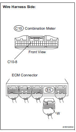
(a) Disconnect the E5 ECM connector.
(b) Disconnect the C10 combination meter connector.
(c) Measure the resistance according to the value(s) in the table below.
Standard resistance (Check for Open)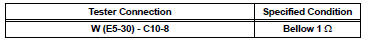
Standard resistance (Check for Short)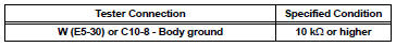
(d) Reconnect the ECM connector.
(e) Reconnect the combination meter connector.

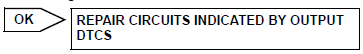
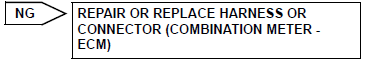
REPAIR OR REPLACE HARNESS OR CONNECTOR (COMBINATION METER - ECM)
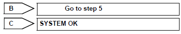
5 CHECK THAT ENGINE STARTS
(a) Turn the ignition switch to the ON position.
(b) Start the engine.
Result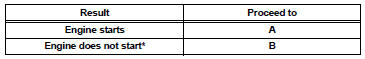
HINT: *: The intelligent tester cannot communicate with the ECM.

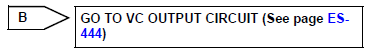
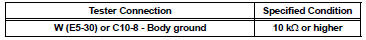
6 CHECK HARNESS AND CONNECTOR (COMBINATION METER - BODY GROUND)
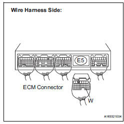
(a) Disconnect the E5 ECM connector.
(b) Turn the ignition switch to the ON position.
(c) Measure the voltage according to the value(s) in the table below.
Standard voltage 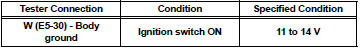
(d) Reconnect the ECM connector.

7 CHECK HARNESS AND CONNECTOR (COMBINATION METER - ECM)
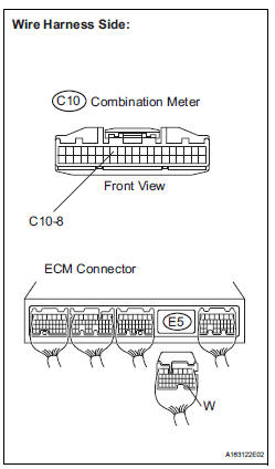
(a) Disconnect the E5 ECM connector.
(b) Disconnect the C10 combination meter connector.
(c) Measure the resistance according to the value(s) in the table below.
Standard resistance (Check for short)
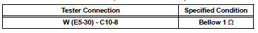
Standard resistance (Check for Short)
(d) Reconnect the ECM connector.
(e) Reconnect the combination meter connector

REPLACE COMBINATION METER ASSEMBLY
 Air Intake Control Circuit
DESCRIPTION
The air cleaner is equipped with two inlets, one of which is opened or closed
by the Air Intake Control
Valve (AICV). This system reduces intake noise and increases engine power at
l ...
 Сamshaft timing oil control valve assembly
COMPONENTS
ON-VEHICLE INSPECTION
1. INSPECT CAMSHAFT TIMING CONTROL VALVE ASSEMBLY
(a) Connect the intelligent tester to the DLC3.
(b) Turn the ignition switch to the ON position ...
Other materials:
USE SIMULATION METHOD TO CHECK
DTC B0113/42 Short to B+ in Side Squib RH Circuit
DESCRIPTION
The side squib RH circuit consists of the center airbag sensor assembly and
the front seat side airbag
assembly RH.
This circuit instructs the SRS to deploy when deployment conditions are met.
DTC B0113/42 is recorded when a sh ...
Removal
1. REMOVE FRONT WHEELS
2. REMOVE FRONT STABILIZER LINK ASSEMBLY LH
(a) Remove the 2 nuts and front stabilizer link assembly
LH.
HINT:
If the ball joint turns together with the nut, use a
hexagon (6 mm) wrench to hold the stud.
3. REMOVE FRONT STABILIZER LINK ASSEMBLY RH
HINT:
Remove the ...
Removal
1. REMOVE REAR SEAT 3 POINT TYPE BELT
ASSEMBLY (for 8-Passenger)
HINT:
Refer to the instructions for disassembly of the rear No. 1
seat assembly (for center seat).
Remove the bolt and rear seat 3 point type belt
assembly.
2. REMOVE REAR SEAT 3 POINT TYPE BELT
ASSEMBLY (for 7-Pass ...
