Toyota Sienna Service Manual: On-vehicle inspection
1. CONNECT INTELLIGENT TESTER
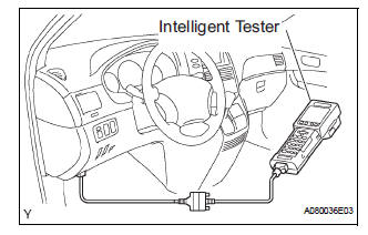
(a) Connect the intelligent tester to the DLC3.
(b) Start the engine and run at idle.
(c) Select the ACTIVE TEST mode on the intelligent tester.
HINT: Please refer to the intelligent tester operator's manual for further details.
2. INSPECT ACTUATOR MOTOR OPERATION
(a) With the motor relay on, check the actuator motor operation noise.
(b) Turn the motor relay off.
(c) Depress the brake pedal and hold it for approximately 15 seconds. Check that the brake pedal cannot be depressed.
(d) With the motor relay on, check that the pedal does not pulsate.
NOTICE: Do not keep the motor relay turned on for more than 5 seconds continuously. When operating it continuously, set an interval of more than 20 seconds.
(e) Turn the motor relay off and release the brake pedal.
3. INSPECT RIGHT FRONT WHEEL OPERATION
NOTICE: Never turn on the solenoids in a manner different to those described below
(a) With the brake pedal depressed, perform the following operations.
(b) Turn the SFRH and SFRR solenoids on simultaneously, and check that the pedal cannot be depressed.
NOTICE: Do not keep the solenoid turned on for more than 10 seconds continuously. When operating it continuously, set an interval of more than 20 seconds.
(c) Turn the SFRH and SFRR solenoids off simultaneously, and check that the pedal can be depressed.
(d) Turn the motor relay on, and check that the pedal returns.
NOTICE: Do not keep the motor relay turned on for more than 5 seconds continuously. When operating it continuously, set an interval of more than 20 seconds.
(e) Turn the motor relay off and release the brake pedal.
4. INSPECT OTHER WHEEL OPERATION
(a) Using the same procedure, check the solenoids of the other wheels.
HINT: Left front wheel: SFLH, SFLR Right rear wheel: SRRH, SRRR Left rear wheel: SRLH, SRLR
 Brake actuator (w/o vsc)
COMPONENTS
...
 Removal
1. DRAIN BRAKE FLUID
NOTICE:
Wash brake fluid off immediately if it adheres to any
painted surface.
2. DISCONNECT BATTERY NEGATIVE TERMINAL
3. REMOVE AIR CLEANER ASSEMBLY WITH HOSE
4. REMOVE BRA ...
Other materials:
Brake Warning Light Remains ON
DESCRIPTION
If the ECU detects a trouble, it turns on the brake warning light at the same
time of prohibiting ABS
control.
At this time, the ECU records a DTC in memory.
Connect terminals TC and CG of the DLC3 to make the brake warning light blink
and output the DTC.
WIRING DIAGRAM
...
Scratched / Reversed Disc
DTC 62-46 Scratched / Reversed Disc
DTC 63-46 Scratched / Reversed Disc
DESCRIPTION
DTC No.
DTC Detecting Condition
Trouble Area
62-46
Scratches or dirt is found on CD surface or CD is set
upside down.
CD
Radio receiver
...
Sensor detection display, obstacle distance
Distance display
Sensors that detect an obstacle will illuminate continuously or blink.
*1: The images may differ from that shown in the illustrations.
*2: Multi-information display
*3: Audio system screen
Buzzer operation and distance to an obstacle
A buzzer sounds when the sensors are o ...
