Toyota Sienna Service Manual: Open in CAN Main Bus Line
DESCRIPTION
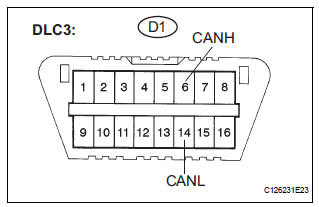
There may be an open circuit in the CAN main bus wire and/or the DLC3 branch wire when the resistance between terminals 6 (CANH) and 14 (CANL) of the DLC3 is 69 Ω or higher.
|
Symptom |
Trouble Area |
| Resistance between terminals 6 (CANH) and 14 (CANL) of the DLC3 is 69 Ω or higher. |
|
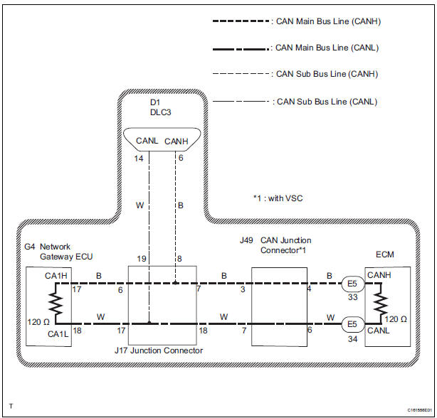
WIRING DIAGRAM
INSPECTION PROCEDURE
NOTICE:
- Turn the ignition switch off before measuring the resistances of CAN bus main wires and CAN bus branch wires
- After the ignition switch is turned off, check that the key reminder warning system and light reminder warning system are not in operation.
- Before measuring the resistance, leave the vehicle as is for at least 1 minute and do not operate the ignition switch, any other switches, or the doors. If any doors need to be opened in order to check connectors, open the doors and leave them open.
HINT: Operating the ignition switch, any switches, or any doors triggers related ECU and sensor communication with the CAN. This communication will cause the resistance value to change
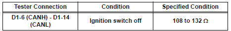
1 CHECK DLC3
- Turn the ignition switch off.
- Measure the resistance according to the value(s) in the table below.
Standard resistance
Result
NOTICE: When the measured value is 133 Ω or more and a CAN communication system diagnostic trouble code is output, there may be a fault besides disconnection of the DLC3 branch wire. For that reason, troubleshooting should be performed again from "HOW TO PROCEED WITH TROUBLESHOOTING" (See page CA-7 ) after repairing the trouble area.
2 CHECK FOR OPEN IN CAN BUS MAIN WIRE (ECM CAN MAIN BUS WIRE)
- Turn the ignition switch off.
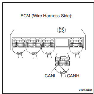
- Disconnect the ECM connector.
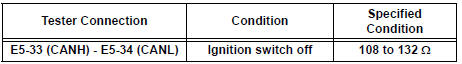
- Measure the resistance according to the value(s) in the table below.
Standard resistance
REPLACE ECM
3 CHECK FOR OPEN IN CAN BUS MAIN WIRE (NETWORK GATEWAY ECU CAN MAIN BUS WIRE)
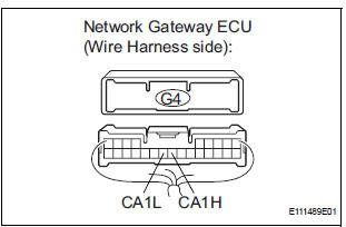
- Reconnect the ECM connector.
- Disconnect the network gateway ECU connector.
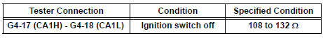
- Measure the resistance according to the value(s) in the table below.
Standard resistance
REPLACE NETWORK GATEWAY ECU
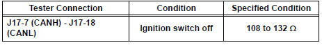
4 CHECK FOR OPEN IN CAN BUS MAIN WIRE (JUNCTION CONNECTOR - NETWORK GATEWAY ECU)
- Reconnect the network gateway ECU connector.
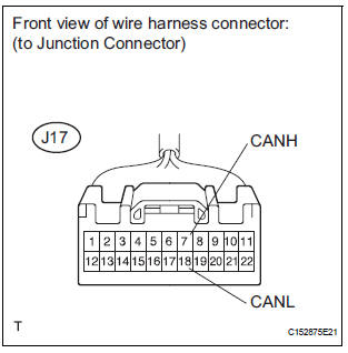
- Disconnect the junction connector (J17).
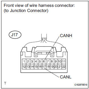
- Measure the resistance according to the value(s) in the table below.
Standard resistance
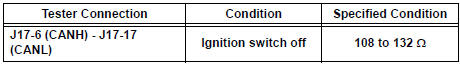
Result
5 CHECK CHECK FOR OPEN IN CANBUS MAIN WIRE (JUNCTION CONNECTOR - ECM)
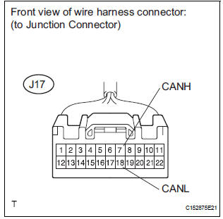
- Measure the resistance according to the value(s) in the table below.
Standard resistance
REPLACE WIRING HARNESS CONNECTOR (JUNCTION CONNECTOR)
6 CHECK FOR OPEN IN CAN BUS MAIN WIRE (JUNCTION CONNECTOR -Å@CAN JUNCTION CONNECTOR)
- Measure the resistance according to the value(s) in the table below.
Standard resistance
REPLACE WIRING HARNESS CONNECTOR (JUNCTION CONNECTOR)
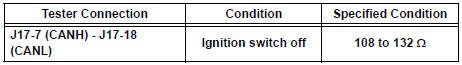
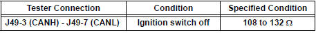
7 CHECK FOR OPEN IN CAN BUS MAIN WIRE (CAN JUNCTION CONNECTOR - JUNCTION CONNECTOR)
- Reconnect the junction connector (J17).
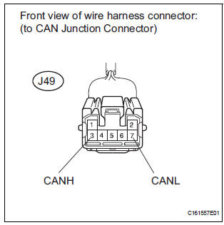
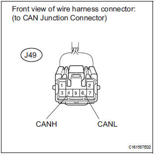
- Disconnect the CAN junction connector (J49).
- Measure the resistance according to the value(s) in the table below.
Standard resistance
8 CHECK FOR OPEN IN CAN BUS MAIN WIRE (CAN JUNCTION CONNECTOR - ECM)
- Measure the resistance according to the value(s) in the table below.
Standard resistance
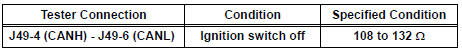
REPLACE WIRING HARNESS CONNECTOR (CAN JUNCTION CONNECTOR)
 CAN Bus Line
DESCRIPTION
When any DTC for the CAN communication system is output, first measure the
resistance between the
terminals of the DLC3 to specify the trouble area, and check that there is no
short ...
 Short in CAN Bus Lines
DESCRIPTION
The CAN bus wires are considered to be shorted when the resistance between
terminals 6 (CANH) and
14 (CANL) of the DLC3 is below 54 Ω.
Symptom
Trouble Area
...
Other materials:
Stowing the third seats (power seats)
You can operate the power third seats when the shift lever is in P.
Before stowing or returning third seat, remove any items from the floor
area to prevent interference with moving parts.
Before stowing the third seats
Lower the center head
restraint to the lowest position and stow th ...
On-vehicle inspection
1. INSPECT STEERING PAD (VEHICLE NOT INVOLVED IN COLLISION)
Perform a diagnostic system check.
With the steering pad installed on the vehicle,
perform a visual check. If there are any defects as
mentioned below, replace the steering pad with a
new one:
Cuts, minute cracks or marked ...
Rear Air Outlet Damper Position Sensor Circuit
DESCRIPTION
This sensor detects the position of the rear air outlet control servo motor
and sends the appropriate
signals to the A/C amplifier. The position sensor is built in the rear air
outlet control servo motor.
The position sensor's resistance changes as the rear air outlet contro ...
