Toyota Sienna Service Manual: Short in CAN Bus Lines
DESCRIPTION
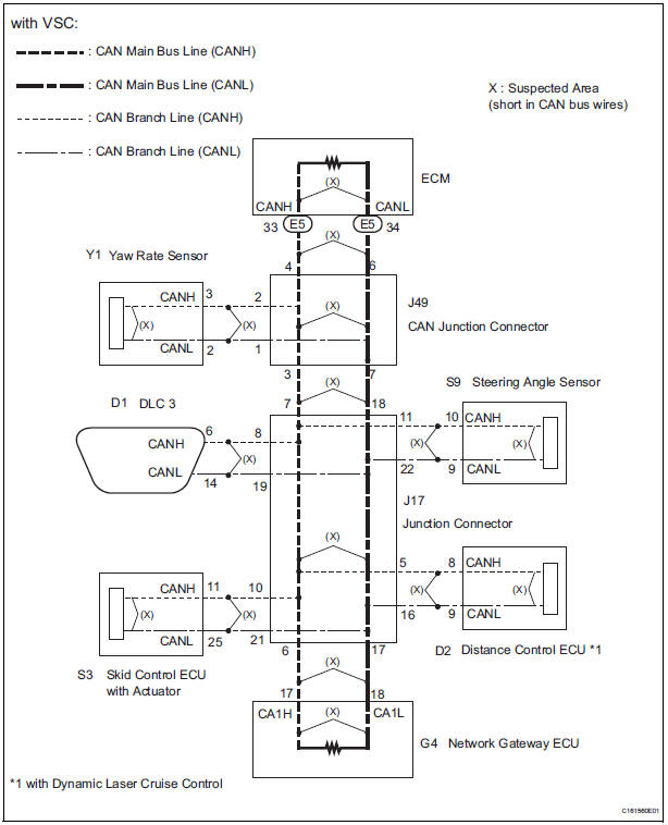
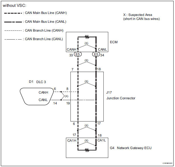
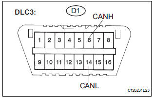
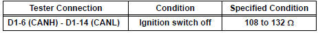
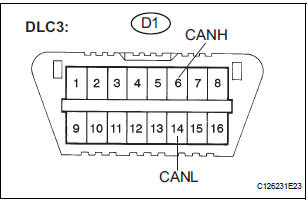
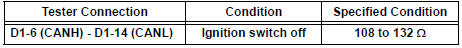
The CAN bus wires are considered to be shorted when the resistance between terminals 6 (CANH) and 14 (CANL) of the DLC3 is below 54 Ω.
|
Symptom |
Trouble Area |
| Resistance between terminals 6 (CANH) and 14 (CANL) of the DLC3 is below 54 Ω. |
|
WIRING DIAGRAM
INSPECTION PROCEDURE
NOTICE:
- Turn the ignition switch off before measuring the resistances of CAN bus main wires and CAN bus branch wires.
- After the ignition switch is turned off, check that the key reminder warning system and light reminder warning system are not in operation.
- Before measuring the resistance, leave the vehicle as is for at least 1 minute and do not operate the ignition switch, any other switches, or the doors. If any doors need to be opened in order to check connectors, open the doors and leave them open.
HINT: Operating the ignition switch, any switches, or any doors triggers related ECU and sensor communication with the CAN. This communication will cause the resistance value to change.
1 CHECK FOR SHORT IN CAN BUS WIRES (ECM MAIN BUS WIRE)
- Turn the ignition switch off.
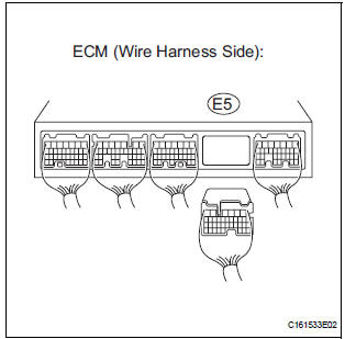
- Disconnect the ECM connector.
- Measure the resistance according to the value(s) in the table below.
Standard resistance
REPLACE ECM
2 CHECK FOR SHORT IN CAN BUS WIRES (NETWORK GATEWAY ECU MAIN BUS WIRE)
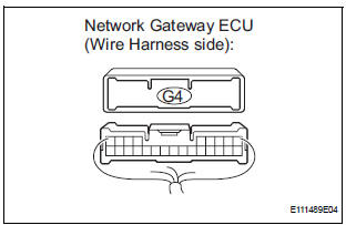
- Disconnect the network gateway ECU connector.
- Measure the resistance according to the value(s) in the table below.
Standard resistance
REPLACE NETWORK GATEWAY ECU
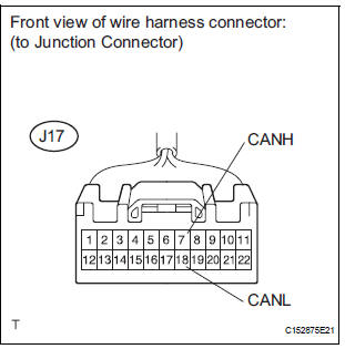
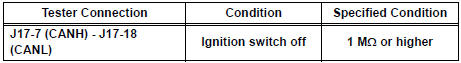
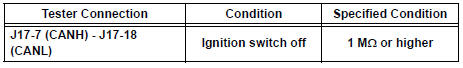
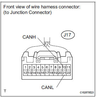
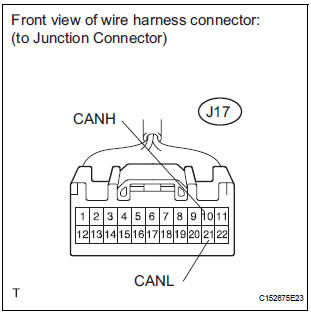
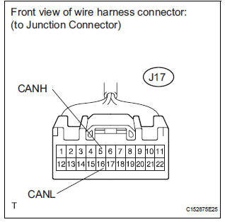
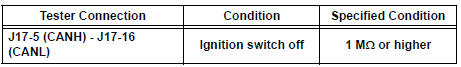
3 CHECK FOR SHORT IN CAN BUS WIRES (DLC3 BRANCH WIRE)
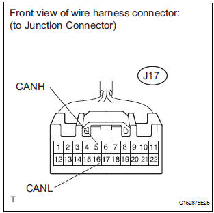
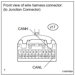
- Disconnect the junction connector (J17).
- Measure the resistance according to the value(s) in the table below.
Standard resistance
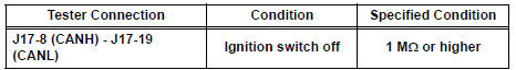
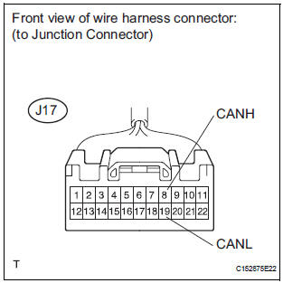
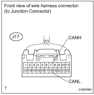
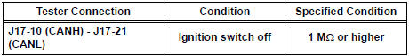
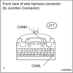
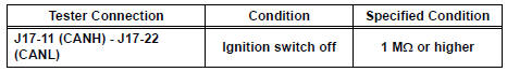
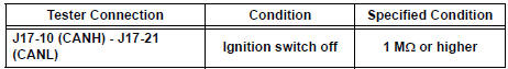
4 CHECK FOR SHORT IN CAN BUS WIRES (JUNCTION CONNECTOR - NETWORK GATEWAY ECU MAIN BUS WIRE)
- Measure the resistance according to the value(s) in the table below.
Standard resistance
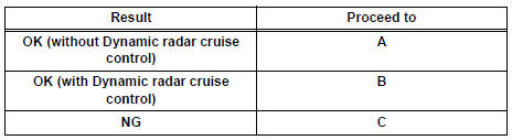
Result
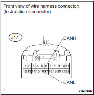
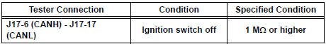
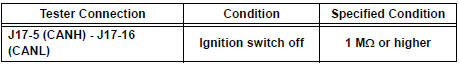
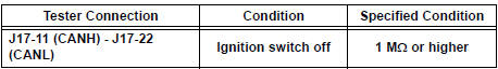
5 CHECK FOR SHORT IN CAN BUS WIRES (JUNCTION CONNECTOR - ECM MAIN BUS WIRE)
- Measure the resistance according to the value(s) in the table below.
Standard resistance
REPLACE WIRING HARNESS CONNECTOR (JUNCTION CONNECTOR)
6 CHECK FOR SHORT IN CAN BUS WIRES (JUNCTION CONNECTOR - CAN JUNCTION CONNECTOR MAIN BUS WIRE)
- Measure the resistance according to the value(s) in the table below.
Standard resistance
7 CHECK FOR SHORT IN CAN BUS WIRES (SKID CONTROL ECU BRANCH WIRE)
- Measure the resistance according to the value(s) in the table below.
Standard resistance
8 CHECK FOR SHORT IN CAN BUS WIRES (STEERING ANGLE SENSOR BRANCH WIRE)
- Measure the resistance according to the value(s) in the table below.
Standard resistance
Result
REPLACE WIRING HARNESS CONNECTOR (JUNCTION CONNECTOR)
9 CHECK FOR SHORT IN CAN BUS WIRES (DISTANCE CONTROL ECU BRANCH WIRE)
- Measure the resistance according to the value(s) in the table below.
Standard resistance
REPLACE WIRING HARNESS CONNECTOR (JUNCTION CONNECTOR)
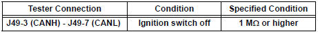
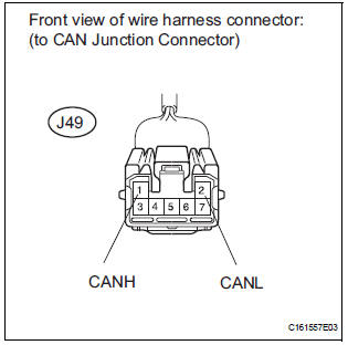
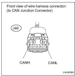
10 CHECK FOR SHORT IN CAN BUS WIRES (CAN JUNCTION CONNECTOR - JUNCTION CONNECTOR MAIN BUS WIRE)
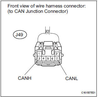
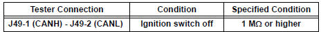
- Disconnect the junction connector (J49).
- Measure the resistance according to the value(s) in the table below.
Standard resistance
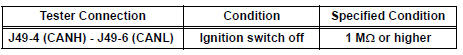
11 CHECK FOR SHORT IN CAN BUS WIRES (CAN JUNCTION CONNECTOR - ECM MAIN BUS WIRE)
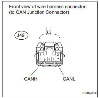
- Measure the resistance according to the value(s) in the table below.
Standard resistance
12 CHECK FOR SHORT IN CAN BUS WIRES (YAW RATE SENSOR BRANCH WIRE)
- Measure the resistance according to the value(s) in the table below.
Standard resistance
REPLACE WIRING HARNESS CONNECTOR (CAN JUNCTION CONNECTOR)
13 CHECK FOR SHORT IN CAN BUS WIRES (SKID CONTROL ECU BRANCH WIRE)
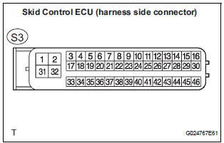
- Disconnect the skid control ECU connector.
- Measure the resistance according to the value(s) in the table below.
Standard resistance
REPLACE ABS & TRACTION ACTUATOR ASSEMBLY
14 CHECK FOR SHORT IN CAN BUS WIRES (STEERING ANGLE SENSOR BRANCH WIRE)
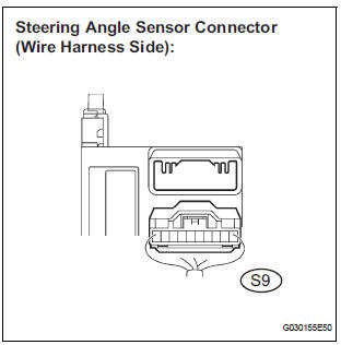
- Disconnect the steering angle sensor connector
- Measure the resistance according to the value(s) in the table below.
Standard resistance
REPLACE STEERING ANGLE SENSOR
15 CHECK FOR SHORT IN CAN BUS WIRES (DISTANCE CONTROL ECU BRANCH WIRE)
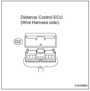
- Disconnect the distance control ECU connector.
- Measure the resistance according to the value(s) in the table below.
Standard resistance
REPLACE DISTANCE CONTROL ECU ASSEMBLY
16 CHECK FOR SHORT IN CAN BUS WIRES (YAW RATE SENSOR BRANCH WIRE)
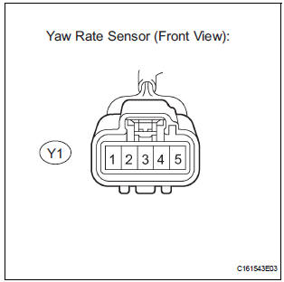
- Disconnect the yaw rate sensor connector.
- Measure the resistance according to the value(s) in the table below.
Standard resistance
REPLACE YAW RATE SENSOR
 Open in CAN Main Bus Line
DESCRIPTION
There may be an open circuit in the CAN main bus wire and/or the DLC3 branch
wire when the resistance
between terminals 6 (CANH) and 14 (CANL) of the DLC3 is 69 Ω or higher.
...
 Short to B+ in CAN Bus Line
DESCRIPTION
A short to B+ is suspected in the CAN bus wire when the resistance between
terminals 6 (CANH) and 16
(BAT), or terminals 14 (CANL) and 16 (BAT) of the DLC3 is below 6 kΩ.
...
Other materials:
Towing with a wheel-lift type truck
From the front (2WD models)
Release the parking brake.
From the front (AWD models)
Use a towing dolly under the rear
wheels.
From the rear
Use a towing dolly under the front
wheels. ...
Short in Driver Side Squib 2nd Step Circuit
DTC B1180/17 Short in Driver Side Squib 2nd Step Circuit
DESCRIPTION
The driver side squib 2nd step circuit consists of the center airbag sensor
assembly, the spiral cable and
the steering pad.
The circuit instructs the SRS to deploy when deployment conditions are met.
DTC B1180/17 is rec ...
Air Intake Control Circuit
DESCRIPTION
The air cleaner is equipped with two inlets, one of which is opened or closed
by the Air Intake Control
Valve (AICV). This system reduces intake noise and increases engine power at
low-to-high engine speed
range.
When the engine is operating in the low-to-mid speed range, this ...
