Toyota Sienna Service Manual: Diagnosis system
1. CHECK DLC3
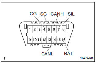
- The vehicle's ECU uses ISO 15765-4 for communication protocol. The terminal arrangement of the DLC3 complies with SAE J1962 and matches the ISO 15765-4 format.
NOTICE: *: Before measuring the resistance, leave the vehicle as is for at least 1 minute and do not operate the ignition switch, any other switches or the doors. If the result is not as specified, the DLC3 may have a malfunction. Repair or replace the harness and connector.
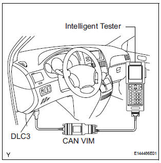
- Connect the cable of the intelligent tester (with CAN VIM) to the DLC3, turn the ignition switch to the ON position and attempt to use the intelligent tester. If the screen displays a communication error message, a problem exists in the vehicle side of the tester side.
HINT:
- If communication is normal when the tool is connected to another vehicle, inspect the DLC3 on the original vehicle.
- If communication is still impossible when the tool is connected to another vehicle, the problem is probably in the tool itself. Consult the Service Department listed in the tool's instruction manual.
 Terminals of ECU
1. CHECK TRANSPONDER KEY AMPLIFIER
Disconnect the I14 amplifier connector and measure
the resistance between the terminal of the wire
harness side connector and body ground.
If the ...
 DTC check / clear
1. CHECK DTC
Connect the intelligent tester to the Controller Area
Network Vehicle Interface Module (CAN VIM). Then
connect the CAN VIM to the DLC3.
Turn the ignition switch ...
Other materials:
Automatic Light Control Sensor Circuit
DESCRIPTION
The Multiplex network body ECU receives the signal from the automatic light
control sensor.
HINT:
DTC code is output when malfunction of automatic light control sensor or open or
short of automatic light
control sensor circuit occurs.
WIRING DIAGRAM
INSPECTION PROCEDURE
...
Installation
1. INSTALL AIR CONDITIONING BLOWER ASSEMBLY
(a) Install the air conditioning blower assembly with the
3 bolts.
Torque: 5.4 N*m (55 kgf*cm, 48 in.*lbf)
NOTICE:
Tighten the bolts in the order shown in the
illustration to install the air conditioning blower
assembly.
2. INSTALL AIR CONDITIO ...
Terminals of ECU
1. FOLD SEAT CONTROL ECU LH
Disconnect the fold seat control ECU connectors.
Measure the voltage and resistance of the wire
harness side connectors.
If the result is not as specified, there may be a
malfunction on the wire harness side.
Reconnect the fold seat control E ...
