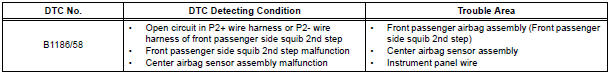
Toyota Sienna Service Manual: Open in Front Passenger Side Squib 2nd Step Circuit
DTC B1186/58 Open in Front Passenger Side Squib 2nd Step Circuit
DESCRIPTION
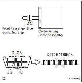
The front passenger side squib 2nd step circuit consists of the center airbag sensor assembly and the front passenger airbag assembly.
The circuit instructs the SRS to deploy when deployment conditions are met.
DTC B1186/58 is recorded when an open circuit is detected in the front passenger side squib 2nd step circuit
WIRING DIAGRAM
INSPECTION PROCEDURE
HINT:
- Perform the simulation method by selecting the "check mode" (signal check) with the intelligent tester.
- After selecting the "check mode" (signal check), perform the simulation method by wiggling each connector of the airbag system or driving the vehicle on a city or rough road
1 CHECK FRONT PASSENGER AIRBAG ASSEMBLY (FRONT PASSENGER SIDE SQUIB 2ND STEP)
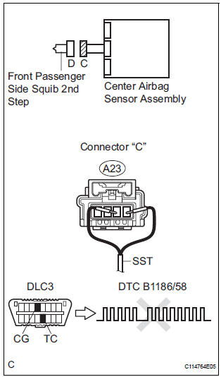
- Turn the ignition switch to the LOCK position.
- Disconnect the negative (-) terminal cable from the battery, and wait for at least 90 seconds.
- Disconnect the connectors from the front passenger airbag assembly.
- Connect the black wire side of SST (resistance 2.1 Ω) to
the instrument panel wire.
CAUTION: Never connect a tester to the front passenger airbag assembly (front passenger side squib 2nd step) for measurement, as this may lead to a serious injury due to airbag deployment.
NOTICE: Do not forcibly insert the SST into the terminals of the connector when connecting.
Insert the SST straight into the terminals of the connector.
SST 09843-18060
- Connect the negative (-) terminal cable to the battery, and wait for at least 2 seconds.
- Turn the ignition switch to the ON position, and wait for at least 60 seconds.
- Clear the DTCs stored in memory.
- Turn the ignition switch to the LOCK position.
- Turn the ignition switch to the ON position, and wait for at least 60 seconds.
- Check the DTCs.
OK: DTC B1186/58 is not output.
HINT: Codes other than DTC B1186/58 may be output at this time, but they are not related to this check.
REPLACE FRONT PASSENGER AIRBAG ASSEMBLY
2 CHECK INSTRUMENT PANEL WIRE (FRONT PASSENGER SIDE SQUIB 2ND STEP CIRCUIT)
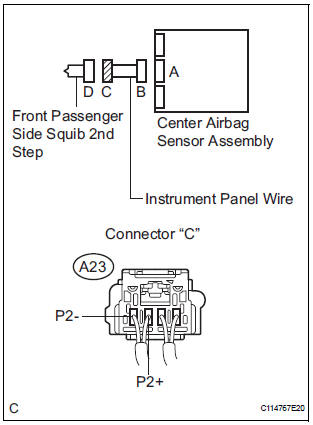
- Turn the ignition switch to the LOCK position.
- Disconnect the negative (-) terminal cable from the battery, and wait for at least 90 seconds.
- Disconnect the SST (resistance 2.1 Ω) from the instrument panel wire.
- Disconnect the connector from the center airbag sensor assembly.
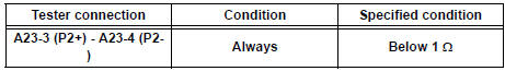
- Measure the resistance according to the value(s) in the table below.
Standard resistance
3 CHECK CENTER AIRBAG SENSOR ASSEMBLY
- Connect the connectors to the front passenger airbag assembly and the center airbag sensor assembly.
- Connect the negative (-) terminal cable to the battery, and wait for at least 2 seconds.
- Turn the ignition switch to the ON position, and wait for at least 60 seconds.
- Clear the DTCs stored in memory.
- Turn the ignition switch to the LOCK position.
- Turn the ignition switch to the ON position, and wait for at least 60 seconds.
- Check the DTCs.
OK: DTC B1186/58 is not output.
HINT: Codes other than DTC B1186/58 may be output at this time, but they are not related to this check.
USE SIMULATION METHOD TO CHECK
 Short in Front Passenger Side Squib 2nd Step
Circuit
Short in Front Passenger Side Squib 2nd Step
Circuit
DTC B1185/57 Short in Front Passenger Side Squib 2nd Step
Circuit
DESCRIPTION
The front passenger side squib 2nd step circuit consists of the center airbag
sensor assembly and the
front passenge ...
 Short to GND in Front Passenger Side Squib
2nd Step Circuit
Short to GND in Front Passenger Side Squib
2nd Step Circuit
DTC B1187/55 Short to GND in Front Passenger Side Squib
2nd Step Circuit
DESCRIPTION
The front passenger side squib 2nd step circuit consists of the center airbag
sensor assembly and the
front p ...
Other materials:
Front Clearance Sonar Sensor LH Circuit
DESCRIPTION
An ultrasonic sensor consists of a sensor portion that transmits and receives
ultrasonic waves and a preamplifier
that amplifies them. The ultrasonic sensor outputs the ultrasonic waves and
sends the received
signals to the clearance warning ECU.
WIRING DIAGRAM
INSPECTION PROC ...
Vehicle Speed Signal Circuit between Stereo Component Amplifier and
Combination Meter
DESCRIPTION
This circuit is necessary for the ASL (Auto Sound Leveliser) built into the
stereo component amplifier.
Speed signals are received from the combination meter and used for the ASL.
The ASL function automatically adjusts the sound data in order to enable hearing
the clear audio ...
Installation with LATCH system (third seat)
Manual seat
Fold the seatback while pulling
the strap. Return the seatback
and secure it at the 1st lock
position (most upright position).
Adjust the seatback to the
11th lock position.
1st lock position
11th lock position
Power seat
Fold down the seatb ...
