Toyota Sienna Service Manual: Operation flow
HINT:
Perform troubleshooting in accordance with the procedures below. The following is an outline of basic troubleshooting procedures. Confirm the troubleshooting procedures for the circuit you are working on before beginning troubleshooting.
- VEHICLE BROUGHT TO WORKSHOP

- CUSTOMER PROBLEM ANALYSIS
- Ask the customer about the conditions and environment when the problem occurred.

- INSPECT BATTERY VOLTAGE
Standard voltage: 11 to 14 V If the voltage is below 11 V, recharge or replace the battery before proceeding.

- SYMPTOM CONFIRMATION AND DTC (AND FREEZE FRAME DATA) CHECK
(a) Visually check the wire harnesses, connectors and fuses for open and short circuits.
(b) Warm up the engine to the normal operating temperature.
(c) Confirm the problem symptoms and conditions, and check for DTCs
Result 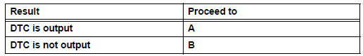
| Go to step 6 |
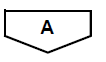
- DTC CHART
- Check the results obtained in step 4. Then find the output DTC in the DTC chart. Look at the "Trouble Area" column for a list of potentially malfunctioning circuits and / or parts.

| Go to step 7 |
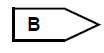
- PROBLEM SYMPTOMS CHART
(a) Check the results obtained in step 4. Then find the problem symptoms in the problem symptoms table. Look at the "Suspected Area" column for a list of potentially malfunctioning circuits and / or parts.

- CIRCUIT INSPECTION OR PARTS INSPECTION
(a) Identify the malfunctioning circuit or part.

- ADJUST, REPAIR OR REPLACE
(a) Adjust, repair or replace the malfunctioning circuit or parts.

- CONFIRMATION TEST
(a) After the adjustment, repairs or replacement, confirm that the malfunction no longer exists. If the malfunction does not reoccur, perform a confirmation test under the same conditions and in the same environment as when the malfunction occurred the first time.

| END |

 Customer problem analysis
HINT:
In troubleshooting, confirm that the problem symptoms
have been accurately identified. Preconceptions should be
discarded in order to make an accurate judgment. To
clearly understand w ...
Other materials:
Types of child restraints
Child restraint systems are classified into the following 3 types
according to the age and size of the child:
Rear facing - Infant seat/convertible seat
Forward facing - Convertible seat
Booster seat
Selecting an appropriate child restraint system
Use a child rest ...
Crankshaft Position Sensor
DESCRIPTION
The Crankshaft Position (CKP) sensor system consists of a CKP sensor plate
and a pickup coil. The
sensor plate has 34 teeth and is installed on the crankshaft. The pickup coil is
made of an iron core and a
magnet.
The sensor plate rotates as each tooth passes through the pi ...
Manual Up / Down Function does not Operate on Rear RH Only
DESCRIPTION
If the manual UP/DOWN function does not operate, the power window motor, the
regulator switch or the
wire harness may be malfunctioning.
WIRING DIAGRAM
INSPECTION PROCEDURE
1 CHECK WIRE HARNESS (POWER SOURCE)
Disconnect the P39 regulator switch connector.
Turn ...
