Toyota Sienna Service Manual: Removal
1. REMOVE FRONT WHEEL
2. REMOVE REAR WHEEL
3. REMOVE TIRE PRESSURE WARNING VALVE AND TRANSMITTER
(a) Remove the valve core and cap, and release the air from the tire.
(b) After ensuring that a sufficient amount of air has been released, remove the nut and washer that are used to secure the tire pressure warning valve and transmitter. Drop the tire pressure warning valve and transmitter inside the tire.
HINT: Keep the removed cap, valve core, nut, and washer.
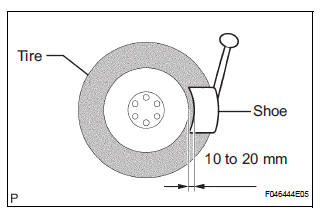
(c) After dropping the tire pressure warning valve and transmitter into the tire, disengage the bead using the shoe of the tire remover.
NOTICE: Be careful not to damage the tire pressure warning valve and transmitter due to interference between the valve and the tire bead.
(d) Remove the bead on the upper side in the usual way.
(e) Take out the tire pressure warning valve and transmitter from the tire and remove the bead on the lower side in the usual way.
NOTICE: If replacing the tire pressure warning valve and transmitter, make sure that a new grommet and a new washer are used.
 Tire pressure warning valve and transmitter
Components
...
 Installation
1. INSTALL TIRE PRESSURE WARNING VALVE AND TRANSMITTER
(a) Insert the tire pressure warning valve and
transmitter into the valve installation hole. Insert it
from the inside of the rim so that ...
Other materials:
Hood
COMPONENTS
Adjustment
HINT:
Since a centering bolt is used as a hood hinge mounting bolt
and hood lock mounting bolt, the hood and hood lock can not
be adjusted with them on. Substitute a bolt with a washer for
the centering bolt.
1. INSPECT HOOD SUB-ASSEMBLY
Check that the clearance is ...
Installation
1. INSTALL FRONT SHOCK ABSORBER WITH COIL SPRING
(a) Install the front shock absorber with coil spring as
shown in the illustration.
(b) Install the 3 nuts to the upper side of the front shock
absorber with coil spring.
Torque: 80 N*m (816 kgf*cm, 59 ft.*lbf)
(c) Install the 2 bolt ...
GPS Receiver Error
DTC 58-11 GPS Receiver Error
DTC 80-11 GPS Receiver Error
DESCRIPTION
DTC No.
DTC Detection Condition
Trouble Area
58-11
RTC, ROM, and RAM of the GPS receiver and
TCXO error
GPS receiver is failed
Radio and navigation assembly ...
