Toyota Sienna Service Manual: Disassembly
1. REMOVE SIDE DEFROSTER NOZZLE DUCT NO.1
(a) Remove the 2 screws <C> and defroster nozzle duct No. 1.
2. REMOVE SIDE DEFROSTER NOZZLE DUCT NO.2
(a) Remove the 2 screws <C> and defroster nozzle duct No. 2.
3. REMOVE DEFROSTER NOZZLE ASSEMBLY
(a) Remove the 4 screws <C> and defroster nozzle assembly.
4. REMOVE HEATER TO REGISTER DUCT NO.1
(a) Remove the 3 screws <C> and heater to register duct No. 1.
5. REMOVE HEATER TO REGISTER DUCT NO.2
(a) Remove the 3 screws <C> and heater to register duct No. 2.
6. REMOVE HEATER TO REGISTER DUCT NO.3
(a) Remove the 2 screws <C> and heater to register duct No. 3.
7. REMOVE SIDE DEFROSTER NOZZLE LH
8. REMOVE SIDE DEFROSTER NOZZLE RH
9. REMOVE INSTRUMENT PANEL FINISH PANEL RETAINER LOWER NO.3
(a) Remove the 2 screws <C> and instrument panel finish panel retainer lower No. 3.
10. REMOVE INSTRUMENT CLUSTER FINISH PANEL REINFORCEMENT
(a) Remove the screw <C> and instrument cluster finish panel reinforcement.
11. REMOVE DEFROSTER DUCT BRACKET NO.1
(a) Remove the screw <C> and defroster duct bracket No. 1.
12. REMOVE INSTRUMENT FINISH PANEL RETAINER LOWER
(a) Remove the screw <C> and instrument finish panel retainer lower.
13. REMOVE INSTRUMENT FINISH PANEL RETAINER LOWER NO.2
(a) Remove the screw <C> and instrument finish panel retainer lower No. 2.
14. REMOVE INSTRUMENT PANEL FINISH PANEL RETAINER NO.1
(a) Remove the 2 screws <C> and instrument panel finish panel retainer No. 1.
15. REMOVE INSTRUMENT PANEL BOX DOOR SUBASSEMBLY NO.2
16. REMOVE ANTENNA CORD SUB-ASSEMBLY
17. REMOVE NAVIGATION ANTENNA ASSEMBLY (w/ Navigation System)
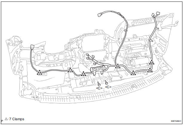
18. REMOVE INSTRUMENT PANEL WIRE NO.2
- Remove the 2 screws <C>.
- Disengage the 7 clamps and remove the instrument panel wire No. 2.
19. REMOVE INSTR PNL PASS L/DOOR AIR BAG ASSEMBLY
 Removal
1. BOLT, SCREW AND NUT TABLE
The bolts, the screws and the nuts, which are
necessary for installation and removal of the
instrument panel are shown in the illustration below
with alpha ...
 Reassembly
1. INSTALL INSTR PNL PASS L/DOOR AIR BAG
ASSEMBLY
2. INSTALL INSTRUMENT PANEL WIRE NO.2
3. INSTALL NAVIGATION ANTENNA ASSEMBLY
4. INSTALL ANTENNA CORD SUB-ASSEMBLY
5. INSTALL INSTRUMENT PANEL BOX ...
Other materials:
Engine front oil seal
COMPONENTS
REMOVAL
1. REMOVE FRONT WHEEL RH
2. REMOVE FRONT FENDER APRON SEAL RH (See
page EM-26)
3. REMOVE V-RIBBED BELT (See page EM-6)
4. REMOVE CRANKSHAFT PULLEY
(a) Using SST, loosen the crankshaft pulley bolt.
SST 09213-70011 (09213-70020), 09330-00021
(b) Using SST, remove ...
Installation
1. INSTALL SIDE REAR WINDOW WEATHERSTRIP LH
2. INSTALL QUARTER WINDOW LOCK ASSEMBLY LH
3. INSTALL POWER VENT WINDOW MOTOR
ASSEMBLY LH
4. INSTALL SIDE WINDOW ASSEMBLY REAR LH
5. INSTALL RR WINDOW SIDE GARNISH ASSEMBLY
LH
6. INSTALL RR WINDOW SIDE GARNISH ASSEMBLY
NO.2 LH
7. REMOVE QUARTER TR ...
On-vehicle inspection
1. INSPECT THROTTLE BODY
Listen to the throttle control motor operating sounds.
Turn the ignition switch to the ON position.
When pressing the accelerator pedal position
sensor lever, listen to the running motor. Make
sure that no friction noise comes from the
motor.
...
