Toyota Sienna Service Manual: Park / Neutral Position Switch Circuit
DESCRIPTION
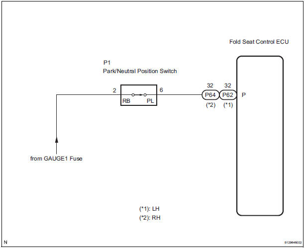
The fold seat control ECU receives signals from the Park/Neutral position switch and controls the seat stowing and return operations. If the shift lever is in any position other than P the seat cannot be operated.
If the ignition switch is in ACC or IG the seat cannot be operated.
WIRING DIAGRAM
INSPECTION PROCEDURE
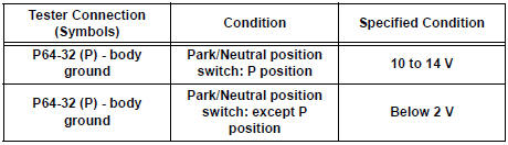
1 INSPECT FOLD SEAT CONTROL ECU
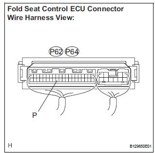
- Remove the fold seat control ECU with connectors still connected.
- Turn the ignition switch ON.
- Measure the voltage according to the value(s) in the table below.
Standard voltage: LH side
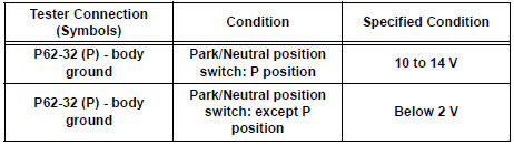
RH side
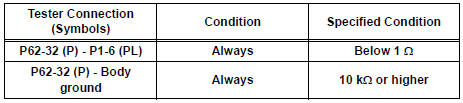
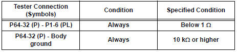
2 CHECK HARNESS AND CONNECTOR (FOLD SEAT CONTROL ECU - PARK/NEUTRAL POSITION SWITCH)
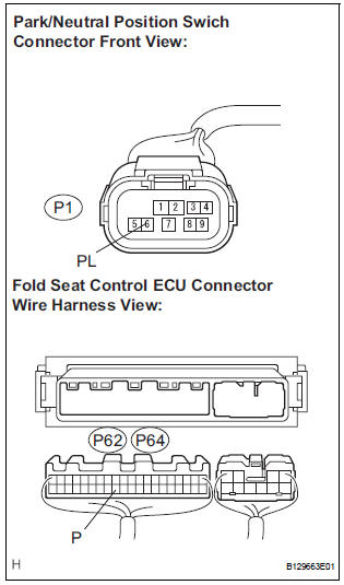
- Disconnect the connector from the park/neutral position switch.
- Disconnect the connectors from the fold seat control ECU.
- Measure the resistance according to the value(s) in the table below.
Standard resistance: LH side
RH side
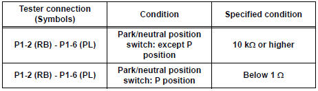
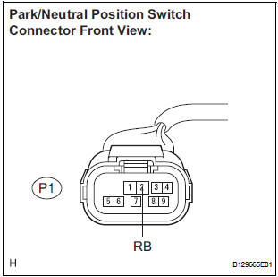
3 INSPECT PARK/NEUTRAL POSITION SWITCH
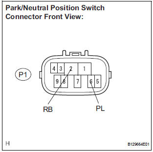
- Remove the park/neutral position switch.
- Measure the resistance according to the value(s) in the table below.
Standard resistance
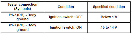
4 CHECK HARNESS AND CONNECTOR (PARK/NEUTRAL POSITION SWITCH - BATTERY)
- Measure the voltage according to the value(s) in the table below.
Standard voltage
REPLACE FOLD SEAT CONTROL ECU
 On-vehicle inspection
1. CHECK POWER REAR NO. 2 SEAT with STOWING FUNCTION
Check the basic functions.
Operate the fold seat switch and power rear
No.2 seat switch and check to make sure each
seat ...
 Back Door Courtesy Switch Circuit
DESCRIPTION
The fold seat control ECU receives signals from the back door courtesy switch
and detects the state of the
back door (open/close). If the ECU does not detect that the back door is open ...
Other materials:
Master Error
DTC 01-DF Master Error
DESCRIPTION
DTC No.
DTC Detection Condition
Trouble Area
01-DF
*1
The device with a display fails and the master is
switched to the audio device.
Also when a communication error between sub-master
(audio) and master occu ...
Installation
HINT:
Install the RH side by the same procedure as the LH side.
1. INSTALL REAR SPEED SENSOR
(a) Clean the contacting surface of the axle hub and a
new skid control sensor.
NOTICE:
Keep the sensor rotor clean.
(b) Place the speed sensor on the axle hub so that the
connector is positioned ...
Scratched / Reversed Disc
DTC 62-46 Scratched / Reversed Disc
DTC 63-46 Scratched / Reversed Disc
DESCRIPTION
DTC No.
DTC Detecting Condition
Trouble Area
62-46
Scratches or dirt is found on CD surface or CD is set
upside down.
CD
Radio receiver
...
