Toyota Sienna Service Manual: Power Windows do not Operate at All
DESCRIPTION
If all of the door windows do not operate, no power may be supplied to the power window master switch or the power window master switch itself may have a malfunction.
WIRING DIAGRAM
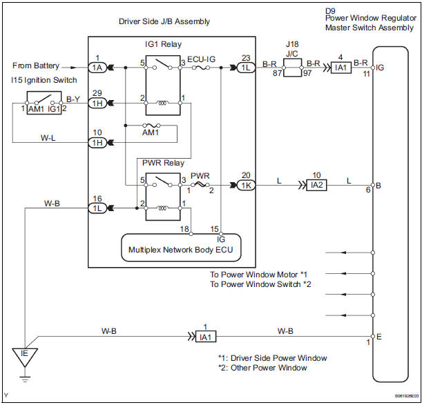
INSPECTION PROCEDURE
1 INSPECT FUSE (PWR, ECU-IG, AM1)
- Remove the fuses from the driver side J/B.
- Check the resistance.
Standard resistance: Below 1 Ω
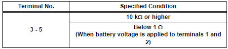
2 INSPECT RELAY (IG1, PWR)
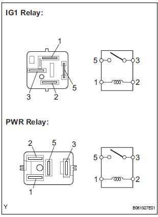
- Remove the relay from the driver side J/B.
- Check the resistance of the relay.
Standard resistance
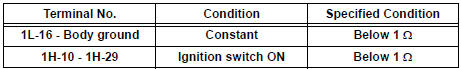
3 CHECK WIRE HARNESS (TO DRIVER SIDE JUNCTION BLOCK ASSEMBLY)
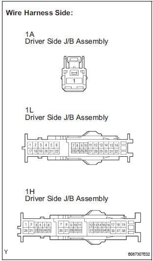
- Disconnect the 1A, 1H and 1L J/B connectors.
- Check the voltage and resistance between each terminal of the wire harness side connector and the body ground.
Standard voltage
Standard resistance
4 CHECK WIRE HARNESS (TO POWER WINDOW REGULATOR MASTER SWITCH)
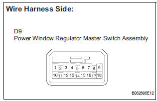
- Disconnect the D9 master switch connector.
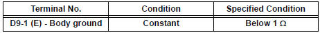
- Check the voltage or resistance between each terminal of the wire harness side connector and the body ground.
Standard voltage
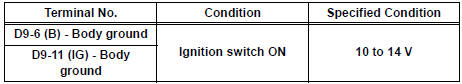
Standard resistance
5 CHECK WIRE HARNESS (DRIVER SIDE JUNCTION BLOCK - POWER WINDOW MASTER SWITCH)
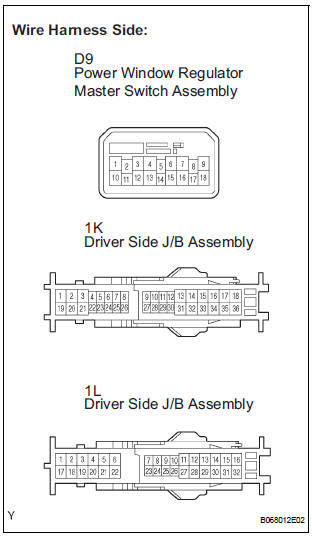
- Disconnect the 1L and 1K J/B connectors.
- Disconnect the D9 master switch connector.
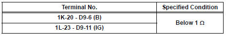
- Check the resistance between the wire harness side connectors.
Standard resistance
REPLACE DRIVER SIDE JUNCTION BLOCK ASSEMBLY
 Manual Up / Down Function does not Operate on Rear RH Only
DESCRIPTION
If the manual UP/DOWN function does not operate, the power window motor, the
regulator switch or the
wire harness may be malfunctioning.
WIRING DIAGRAM
INSPECTION PROCEDURE
1 CH ...
 Power Window can be Operated After Ignition Switch is Turned OFF
Even if Operative Conditions are not Met
Power Window can be Operated After Ignition Switch is Turned OFF
Even if Operative Conditions are not Met
DESCRIPTION
The multiplex network body ECU controls power supplied to the power window
master switch and each
regulator switch continuously for 45 seconds after the ignition switch is turned
OFF ...
Other materials:
Problem symptoms table
RESULT LIST OF CHECK CAN BUS LINE
Symptom
Suspected Area
All ECUs and sensors connected to the CAN
communication system are not displayed on intelligent
tester
CAN Bus Line
The result of "CAN BUS WIRE CHECK" is "Open in
CAN Main Bus Lin ...
ABS Warning Light Remains ON
DESCRIPTION
If any of the following is detected, the ABS warning light remains on.
The skid control ECU connectors are disconnected from the skid control
ECU.
There is a malfunction in the skid control ECU internal circuit.
There is an open in the harness between the combination meter an ...
Starting the engine
Check that the parking brake is set.
Check that the shift lever is set in P.
Firmly depress the brake pedal.
The engine switch indicator will turn green. If the indicator does not turn
green, the engine cannot be started.
Press the engine switch.
The engine will crank until it sta ...
