
Toyota Sienna Service Manual: Power mirror control system (w/o Memory)
PARTS LOCATION
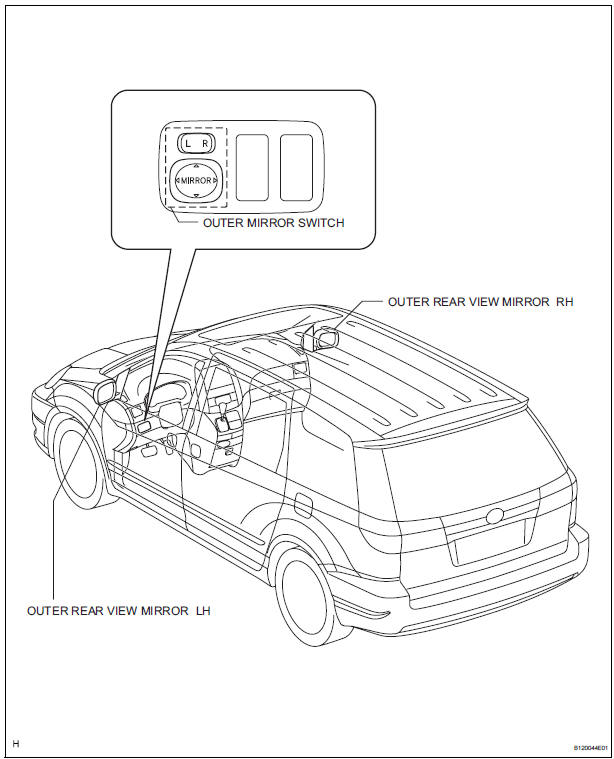
Problem symptoms table
POWER MIRROR CONTROL SYSTEM
|
Symptom |
Suspected area |
| Mirror does not operate |
|
| Mirror operates abnormally |
|
 Power Source Circuit
DESCRIPTION
This is the power source circuit for the outer mirror control ECU.
WIRING DIAGRAM
INSPECTION PROCEDURE
1 INSPECT OUTER MIRROR CONTROL ECU (POWER SOURCE)
Disconnect the O9 o ...
 Inner rear view mirror
COMPONENTS
REMOVAL
1. REMOVE INNER REAR VIEW MIRROR ASSEMBLY
w/ EC mirror:
Remove the inner rear view mirror cover.
w/ EC mirror:
Disconnect the connector.
Remove ...
Other materials:
Warning lights and
indicators
The warning lights and indicators on the instrument cluster and
center panel inform the driver of the status of the vehicle’s various
systems.
For the purpose of explanation, the following illustration displays
all warning lights and indicators illuminated.
Vehicles with monochrome displ ...
Power back door system
PARTS LOCATION
...
Programming the HomeLink® (for U.S.A. owners)
The HomeLink® compatible transceiver in your vehicle has 3 buttons
which can be programmed to operate 3 different devices. Refer to the
programming method below appropriate for the device.
Indicator light
Buttons
Programming the HomeLink®
Point the remote control for
the d ...
