Toyota Sienna Service Manual: Inner rear view mirror
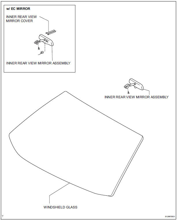
COMPONENTS
REMOVAL
1. REMOVE INNER REAR VIEW MIRROR ASSEMBLY
- w/ EC mirror: Remove the inner rear view mirror cover.
- w/ EC mirror: Disconnect the connector.
- Remove the screw.
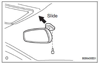
- Remove the inner rear view mirror assembly as shown in the illustration.
INSPECTION
1. INSPECT INNER REAR VIEW MIRROR ASSEMBLY
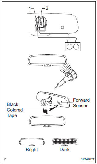
- Inspect operation of the electrochromic inner mirror.
- Connect the positive (+) lead from the battery to terminal 1 and connect the negative (-) lead to terminal 2.
- Attach black colored tape to the forward sensor to prevent it from sensing.
- Light up the mirror with an electric light and check that the mirror surface changes from bright to dark.
Standard: Mirror surface changes from bright to dark
If the result is not as specified, replace the mirror assembly.
INSTALLATION
1. INSTALL INNER REAR VIEW MIRROR ASSEMBLY
 Power mirror control system (w/o Memory)
PARTS LOCATION
Problem symptoms table
POWER MIRROR CONTROL SYSTEM
Symptom
Suspected area
Mirror does not operate
Outer mirror switch assembly
Outer r ...
 Outer rear view mirror
COMPONENTS
...
Other materials:
Initialization
1. RESET SLIDING ROOF MOTOR
If the AUTO operation function does not operate,
reset the sliding roof motor using any of the
following methods.
Press the sliding roof switch on the TILT UP side
and hold it until the sliding roof motor stops.
Then release the switch and leave it untou ...
Master Cylinder Pressure Sensor Malfunction
DTC C1246/46 Master Cylinder Pressure Sensor Malfunction
DESCRIPTION
Master cylinder pressure sensor is connected to the skid control ECU in the
actuator.
INSPECTION PROCEDURE
1 READ VALUE ON INTELLIGENT TESTER (MASTER CYLINDER PRESSURE SENSOR)
(a) Connect the intelligent tester to the DL ...
Active head restraints
When the occupantŌĆÖs lower back
presses against the seatback during
a rear-end collision, the head
restraint moves slightly forward
and upward to help reduce the
risk of whiplash on the seat occupant
Active head restraints
Even small forces applied to the seatback may cause the head rest ...
