Toyota Sienna Service Manual: Power Source Circuit
DESCRIPTION
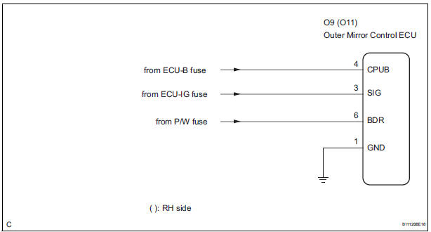
This is the power source circuit for the outer mirror control ECU.
WIRING DIAGRAM
INSPECTION PROCEDURE
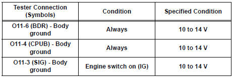
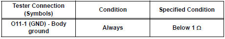
1 INSPECT OUTER MIRROR CONTROL ECU (POWER SOURCE)
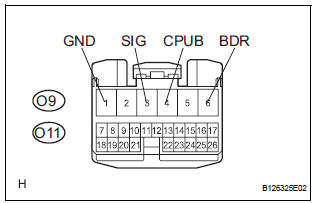
- Disconnect the O9 or O11 ECU connector.
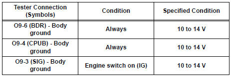
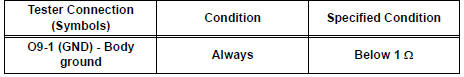
- Measure the voltage and resistance according to the value(s) in the table below.
Outer mirror control ECU LH: Voltage
Resistance
Outer mirror control ECU RH: Voltage
Resistance
PROCEED TO NEXT CIRCUIT INSPECTION SHOWN IN PROBLEM SYMPTOMS TABLE
 Memory Switch Circuit
DESCRIPTION
When the seat memory switch M1 or M2 is pressed, the position control ECU &
switch (Seat ECU)
transmits a signal of the memorized mirror position to the outer mirror control
ECU. ...
 Power mirror control system (w/o Memory)
PARTS LOCATION
Problem symptoms table
POWER MIRROR CONTROL SYSTEM
Symptom
Suspected area
Mirror does not operate
Outer mirror switch assembly
Outer r ...
Other materials:
Data list / active test
HINT:
By accessing the DATA LIST displayed by the intelligent
tester, you can perform such functions as reading the values
of switches and sensors without removing any parts. Reading
the DATA LIST as the first step in troubleshooting is one
method to shorten labor time.
1. DATA LIST FOR OCCUPA ...
EVAP System
RELATED DTCS
If any EVAP system DTCs are set, the malfunctioning area can be determined
using the table below.
NOTICE:
If the 0.02 inch reference pressure difference between the first and
second checks is greater than
the specification, the DTCs corresponding to the refe ...
Installation
1. INSTALL TIMING CHAIN CASE OIL SEAL
(a) Using SST, tap in a new oil seal until its surface is
flush with the timing chain case edge.
SST 09223-22010, 09506-35010
NOTICE:
Keep the lip free from foreign matter.
Do not tap on the oil seal at an angle.
Make sure that the oil ...
