Toyota Sienna Service Manual: Power Slide Door Pulse Sensor Malfunction on Rear Right Door
DTC B2223 Power Slide Door Pulse Sensor Malfunction on Rear Right Door
DESCRIPTION
- A pulse sensor is built into slide door RH for jam and foreign object detection and for slide door position detection. The jam and foreign object detection feature of the pulse sensor monitors the operating speed of the slide door while the power slide door is in operation. The slide door position detection feature of the pulse sensor monitors where the slide door is. If the slide door position detection feature outputs a pulse signal that is out of the normal range, the power slide door ECU RH will set DTC B2223.
- If DTC B2223 is set, the power slide door system will be turned off. Thus, the slide door can be moved freely and will be switched to manual operation mode (not electrically controlled).
- In order to restore the power slide door system to normal operation mode, first solve the problem indicated by DTC B2223 and then manually close the slide door fully (reset operation).
|
DTC No. |
DTC Detection Condition |
Trouble Area |
|
B2223 |
Power slide door RH does not operate |
|
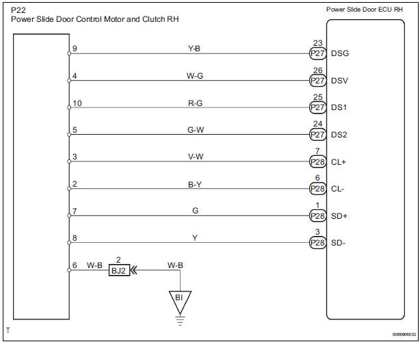
WIRING DIAGRAM
INSPECTION PROCEDURE
1 CHECK WIRE HARNESS (MOTOR AND CLUTCH RH - POWER SLIDE DOOR ECU RH)
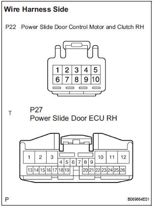
- Disconnect the P22 motor and clutch, and P27 ECU connectors.
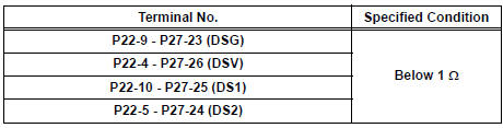
- Check the resistance between the wire harness side connectors.
Resistance (Check for open circuit)
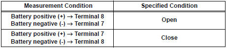
2 INSPECT SLIDE DOOR CONTROL MOTOR AND CLUTCH ASSEMBLY RH
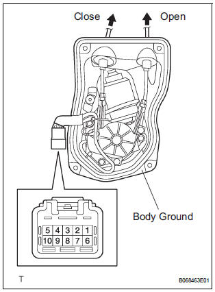
- Remove the motor and clutch.
- Connect the battery positive (+) lead to terminal 3 and battery negative (-) terminal lead to terminal 2.
- Apply battery voltage to the terminals and check the motor operation.
OK
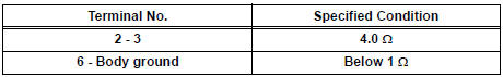
- Check the resistance of the clutch terminals.
Resistance
- Reinstall the motor and clutch with the connector connected.
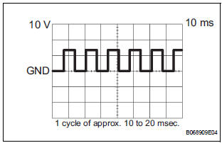
- Check the pulse of the pulse sensor.
- Using an oscilloscope, check the pulse generated when the door is manually opened and closed.
Reference
HINT: A cycle of the pulse changes between approx. 10 to 20 msec. according to the speeds that the slide door is moving.
NOTICE: When disconnecting the control motor and clutch, initialize the power slide door system.
REPLACE POWER SLIDE DOOR ECU RH
 Diagnostic trouble code chart
If a malfunction code is displayed during the DTC check,
check the circuit listed for that code in the table below.
(Proceed to the page given for that circuit.)
POWER SLIDE DOOR SYSTEM
...
 Power Slide Door Pulse Sensor Malfunction on
Rear Left Door
Power Slide Door Pulse Sensor Malfunction on
Rear Left Door
DTC B2224 Power Slide Door Pulse Sensor Malfunction on
Rear Left Door
DESCRIPTION
A pulse sensor is built into slide door LH for jam and foreign
object detection and for slide door posi ...
Other materials:
System description
1. GENERAL
The dynamic laser cruise control system has two
cruise control modes: the constant speed control
mode and vehicle-to-vehicle distance control mode.
The vehicle-to-vehicle distance control mode is
always selected when starting the dynamic laser
cruise control ...
Video terminal
COMPONENTS
REMOVAL
1. REMOVE REAR DOOR SCUFF PLATE LH
2. REMOVE REAR DOOR WEATHERSTRIP LH
3. REMOVE BACK DOOR WEATHERSTRIP
4. REMOVE BACK DOOR SCUFF PLATE
5. REMOVE QUARTER TRIM FRONT PANEL ASSEMBLY LH
6. REMOVE VIDEO(VIDEO ADAPTER) TERMINAL
Release the 4 claw fittings and ...
Rear power window switch
INSPECTION
1. INSPECT POWER WINDOW REGULATOR SWITCH ASSEMBLY REAR
Check the resistance between the switch terminals
when the switch is operated.
Standard
If the result is not as specified, replace the switch
assembly. ...
