Toyota Sienna Service Manual: System description
1. GENERAL
- The dynamic laser cruise control system has two cruise control modes: the constant speed control mode and vehicle-to-vehicle distance control mode.
- The vehicle-to-vehicle distance control mode is always selected when starting the dynamic laser cruise control system.
- Operation of the constant speed control mode is the same as that for a conventional cruise control system.
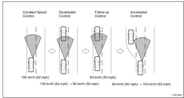
- This system maintains the vehicle running at the speed that the driver has set, as long as there are no vehicles ahead in the same lane. Then, the system maintains the vehicle distance that has been set by the driver. If the system detects a vehicle driving at a slower speed ahead while the driver is driving at a constant speed, it closes the throttle valve to decelerate. If further deceleration is required, the system controls the brake actuator in order to apply the brakes. Thereafter, if there are no vehicles ahead within the set vehicle-to-vehicle distance because either the vehicle ahead or the driver has changed lanes, the system accelerates slowly to reach the set vehicle speed and resumes driving at the constant speed.
- The constant speed control mode is designed to maintain a constant cruising speed. The vehicle-tovehicle distance control mode is designed to control constant speed cruising function, deceleration cruising function, follow-up cruising function, and acceleration cruising function.
- The laser sensor and the distance control ECU control the system while the vehicle-to-vehicle distance control mode is in operation, and send signals to each actuator and ECU.
- In vehicle-to-vehicle distance control mode, the dynamic laser cruise control system receives signals from the yaw rate (deceleration sensor) and the steering angle sensor. Based on these signals, it then estimates curve radius and compensates for information on the preceding vehicle while turning. It can also compensate for the brake control when approaching another vehicle.
- This system judges the presence of a vehicle in front and the distance to it based on the signals from the laser sensor while the vehicle-to-vehicle distance control mode is in operation. Using this information, the system informs the driver of any danger with the warning buzzer, performs brake control, and turns on the stop light when approaching the vehicle in front.
- The following illustration shows a control example under the following conditions: own vehicle speed is 100 km/h (62 mph) and the speed of the vehicle in front is 80 km/h (50 mph). Setting of the vehicle distance can be changed to 3 distances by operating the distance control switch (distance control switch): long (approximately 75 m (240 ft.)), middle (approximately 50 m (160 ft.)), and short (approximately 30 m (105 ft.)) when the vehicle speed is approximately 90 km/h (55 mph).
HINT:
- Vehicle distance increases and decreases in accordance with vehicle speed.
- Controlling condition is indicated on the multiinformation display in the combination meter.
2. FUNCTION OF MAIN COMPONENTS
|
Item |
Outline |
| Combination Meter (CRUISE Main Indicator Light) |
|
| Combination Meter (Master Warning Light) | If the ECM or distance control ECU detects an automatic cancel signal while the vehicle is operating under cruise control, this light comes on to inform the driver |
| Combination Meter (Buzzer) | If the ECM or distance control ECU detects an automatic cancel signal while the vehicle is operating under cruise control, this buzzer sounds only once to inform the driver |
| Combination Meter (Multi-information Display) |
|
| Cruise Control Main Switch (Main Switch) | Turns the cruise control system ON/OFF |
| Cruise Control Main Switch (Control Switch) |
|
| Steering Pad Switch (Distance Control Switch) | While the system is in the vehicle-to-vehicle distance control mode, the driver can operate the steering pad switch (distance control switch) to select the vehicle-to-vehicle distance in three stages: long, middle, and short |
| Stop Light Switch | Detects the depression of the brake pedal and transmits its signal to the ECM |
| Combination Switch (Wiper Switch) | Transmits wiper control switch information to the distance control ECU |
| Laser Sensor | Radiates laser rays forward, uses the reflected rays for detecting the presence of a vehicle in front, vehicle-to-vehicle distance, and relative speed, and transmits this information to the distance control ECU |
| Steering Angle Sensor | Detects the angle and direction of steering and transmits its signal to the distance control ECU |
| Vehicle Speed Sensor (SP1) | A vehicle speed signal which is output from the skid control ECU is sent to the ECM via the meter |
| Yaw Rate Sensor | Detects the yaw rate of the vehicle and transmits its signal to the distance control ECU |
| Brake Actuator (Skid Control ECU) |
|
| Skid Control Buzzer | This buzzer sounds upon receiving a signal from the skid control ECU |
| ECM |
|
| Throttle Position Sensor and Motor | Upon receiving a signal from the ECM, the throttle control motor actuates the throttle valve |
| Distance Control ECU | While the system is in the vehicle-to-vehicle distance control mode, the distance control ECU detects a vehicle in front based on a signal from the laser sensor. Then, the distance control ECU calculates the acceleration or deceleration rate in order to attain the target vehicle-tovehicle distance, and outputs a request signal to the ECM and skid control ECU. |
3. LIMIT CONTROL
- Low speed limit
The lowest possible limit of the speed setting range is set at approximately 28 mph (for USA) or 45 km/h (for Canada). The cruise control system cannot be set when the driving vehicle speed is below the low speed limit. Cruise control operation will be automatically canceled when the vehicle speed decreases below the low speed limit (40 km/h (25 mph)) while the cruise control is in operation. - High speed limit (constant speed control mode)
The highest possible limit of the speed setting range is set at approximately 125 mph (for USA) or 200 km/h (for Canada). The cruise control system will be set at the high speed limit when the cruise control is set and the vehicle speed is over the high speed limit. Also, + (ACCEL)/RES (RESUME) cannot be used to increase speed beyond the high speed limit. - High speed limit (vehicle-to-vehicle distance control
mode)
The highest possible limit of the speed setting range is set at approximately 85 mph (for USA) or 135 km/ h (for Canada).
4. CRUISE CONTROL OPERATION
The cruise control main switch operates 8 functions: SET, - (COAST), TAP-DOWN, RES (RESUME), + (ACCEL), TAP-UP, CANCEL, and MODE. The SET, TAP-DOWN, and - (COAST) functions, and the RES (RESUME), TAP-UP, and + (ACCEL) functions are operated with the same switch. The cruise control main switch assembly is an automatic return type switch which turns on only while operating it in the direction of each arrow and turns off after releasing it. The dynamic laser cruise control system has two cruise control modes: the constant speed control mode and vehicle-to-vehicle distance control mode.
- The vehicle-to-vehicle distance control mode is always selected when starting up the dynamic laser cruise control system.
- Operation of the constant speed control mode is the same as that for a conventional cruise control system.
- MODE CONTROL
Pushing the switch to MODE for more than 1 second while driving with the cruise control main switch on (READY indicator is on) switches the mode to the constant speed control mode. - SET CONTROL (Constant speed control mode)
The vehicle speed is stored and constant speed control is maintained when pushing the switch to - (COAST)/SET while driving with the vehicle speed within the set speed range (between the low and high speed limits) after turning the cruise control main switch on (NORM. indicator is on), and entering the constant speed control mode. - SET CONTROL (Vehicle-to-vehicle distance control
mode)
The vehicle speed is stored and vehicle-to-vehicle control is maintained when pushing the switch to - (COAST)/SET while driving with the cruise control main switch on (READY indicator is on), and vehicle speed is within the set speed range (between the low and high speed limits). - - (COAST) CONTROL (Constant speed control
mode)
When the cruise control main switch is set to - (COAST)/SET and held in that position while the cruise control system is operating, the ECM sends a "throttle valve opening angle 0" demand signal to the cruise control system. Then the vehicle speed, when the cruise control main switch is released, is stored and maintained.HINT: An actual throttle valve opening angle of 0 is not possible due to the idle speed control, etc.
- - (COAST) CONTROL (Vehicle-to-vehicle distance
control mode)
When - (COAST)/SET on the cruise control main switch is pressed and held while the vehicle-tovehicle distance control mode is in operation, the stored vehicle speed decreases by approximately 5 mph (for USA) or 5 km/h (for Canada) per second. - TAP-DOWN CONTROL (Constant speed control
mode)
When tapping down the cruise control main switch to - (COAST)/SET (for approximately 0.6 seconds) while the constant speed control mode is in operation, the stored vehicle speed decreases each time by approximately 1.6 km/h (1 mph). When the cruise control main switch is released from - (COAST)/SET and the difference between the driving and stored vehicle speeds is more than 5 km/h (3 mph), the driving vehicle speed is stored and constant speed control is maintained. - TAP-DOWN CONTROL (Vehicle-to-vehicle distance
control mode)
When tapping down the cruise control main switch to - (COAST)/SET (for approximately 0.6 seconds) while the vehicle-to-vehicle distance control mode is in operation, the stored vehicle speed decreases each time by approximately 5 mph (for USA) or 5 km/h (for Canada). - + (ACCEL) CONTROL (Constant speed control
mode)
The throttle valve motor of the throttle position sensor and motor is instructed by the ECM to open the throttle valve when + (ACCEL)/RES (RESUME) on the cruise control main switch is pressed and held while the constant speed control mode is in operation. When the cruise control main switch is released from + (ACCEL)/RES (RESUME), the vehicle speed is stored and constant speed control is maintained. - + (ACCEL) CONTROL (Vehicle-to-vehicle distance
control mode)
When + (ACCEL)/RES (RESUME) on the cruise control main switch is pressed and held while the vehicle-to-vehicle distance control mode is in operation, the stored vehicle speed increases by approximately 5 mph (for USA) or 5 km/h (for Canada) per second. Pushing the cruise control main switch to + (ACCEL)/RES (RESUME) while following the vehicle in front with the vehicle-tovehicle distance control mode does not increase the actual vehicle speed, but changes only the set vehicle speed. - TAP-UP CONTROL (Constant speed control mode)
When tapping up the cruise control main switch to + (ACCEL)/RES (RESUME) (for approximately 0.6 seconds) while the constant speed control mode is in operation, the stored vehicle speed increases each time by approximately 1.6 km/h (1 mph).However, when the difference between the driving and the stored vehicle speeds is more than 5 km/h (3 mph), the stored vehicle speed will not be changed.
- TAP-UP CONTROL (Vehicle-to-vehicle distance
control mode)
When tapping up the cruise control main switch to + (ACCEL)/RES (RESUME) (for approximately 0.6 seconds) while the vehicle-to-vehicle distance control mode is in operation, the stored vehicle speed increases each time by approximately 5 mph (for USA) or 5 km/h (for Canada) . - MANUAL CANCEL CONTROL
Performing any of the following cancels the cruise control system while it is in operation (the stored vehicle speed in the ECM is maintained).
- Depressing the brake pedal
- Moving the shift lever from the D or 4 to the N, 3, 2 or L position
- Pulling the cruise control main switch to CANCEL
- Turning the cruise control main switch off (the stored vehicle speed in the ECM is not maintained.)
- RES (RESUME) CONTROL
If cruise control operation was canceled with the stop light switch or the CANCEL switch, and even if driving speed is less than the lower speed control limit, pushing the cruise control main switch to + (ACCEL)/RES (RESUME) restores the vehicle speed memorized at the time of cancellation, and maintains constant speed control. This resume operation will occur after the vehicle speed has risen higher than the lower speed control limit. In the constant speed control mode, once the vehicle speed drops below the low speed limit, RESUME operation is possible after accelerating past the low speed limit and pushing the cruise control main switch to + (ACCEL)/RES (RESUME).
5. BRAKE CONTROL
The distance control ECU determines the distance to the vehicle in front, relative speed, target decreasing speed, and deceleration rate. Based on these data, the ECU transmits a brake demand signal to the skid control ECU via the ECM.
6. DOWN SHIFT CONTROL
While the cruise control system is in operation, the transmission may downshift from an overdrive gear on an uphill road. After the downshift, if the system determines that the uphill inclination has become smaller based on the throttle valve opening angle, the transmission automatically returns to an overdrive gear.
7. AUTO CANCEL (FAIL-SAFE)
- If the VSC activates while the vehicle is being driven with cruise control, the cruise control will be cancelled. The stored vehicle speed will remain in the memory.
- This system has an automatic cancellation function (fail-safe)
 Precaution
Keep in mind the following points when inspecting the
dynamic laser cruise control system.
As there is a limitation on the vehicle-to-vehicle distance
controlling capability, do not overl ...
 How to proceed with
troubleshooting
How to proceed with
troubleshooting
HINT:
Use the following procedures to troubleshoot the dynamic
laser cruise control system.
*: Use the intelligent tester
1 VEHICLE BROUGHT TO WORKSHOP
2 CUSTOMER PROBLEM ANALY ...
Other materials:
Removal
HINT:
Use the same procedures for the RH side and LH side.
The procedures listed below are for the LH side.
1. PRECAUTION
CAUTION:
Be sure to read "PRECAUTION" thoroughly before servicing.
2. DISCONNECT CABLE FROM NEGATIVE BATTERY
TERMINAL
CAUTION:
Wait for 90 seconds ...
Data list / active test
HINT:
By accessing the DATA LIST displayed by the intelligent
tester, you can perform such functions as reading the values
of switches and sensors without removing any parts. Reading
the DATA LIST as the first step in troubleshooting is one
method to shorten labor time.
1. DATA LIST FOR OCCUPA ...
Power Slide Door does not Fully Open
DESCRIPTION
When the LH / RH rear window is open 105 mm (5.91 in.) or more,
the slide door half-open stopper is
activated to force the slide door to stop at approximately 105 mm (5.91 in.)
from the fully open position.
This is caused by the jam protection function between the sli ...
