Toyota Sienna 2010-2026 Owners Manual: Summary of the Blind Spot Monitor
The Blind Spot Monitor is a system that has 2 functions:
- The Blind Spot Monitor function Assists the driver in making the decision when changing lanes
- The Rear Cross Traffic Alert function Assists the driver when backing up
These functions use same sensors.
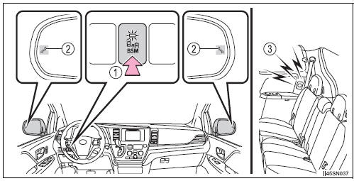
- BSM main switch
Pressing the switch turns the system on or off. When the switch is set to on, the switch’s indicator illuminates. Common switch for Blind Spot Monitor function and Rear Cross Traffic Alert function. - Outside rear view mirror indicator
Blind Spot Monitor function:
When a vehicle is detected in the blind spot, the outside rear view mirror
indicator comes on while the turn signal lever is not operated and the
outside
rear view mirror indicator flashes while the turn signal lever is operated.
Rear Cross Traffic Alert function: When a vehicle approaching from the right or left rear of the vehicle is detected, the outside rear view mirror indicators flash.
- Rear Cross Traffic Alert buzzer (Rear Cross Traffic Alert function
only)
When a vehicle approaching from the right or left rear of the vehicle is detected, a buzzer sounds from behind the rear seat.
The outside rear view mirror indicators visibility
When under strong sunlight, the outside rear view mirror indicator may be difficult to see.
Rear Cross Traffic Alert buzzer hearing
Rear Cross Traffic Alert function may be difficult to hear over loud noises such as high audio volume.
When there is a malfunction in the Blind Spot Monitor system
If a system malfunction is detected due to any of the following reasons, warning message will be displayed:
- There is a malfunction with the sensors
- The sensors have become dirty
- The outside temperature is extremely high or low
- The sensor voltage has become abnormal
Certification for the Blind Spot Monitor system
- For vehicles sold in the U.S.A.
FCC ID: OAYSRR2A
This device complies with part 15 of the FCC Rules. Operation is subject to
the following two conditions:
(1) This device may not cause harmful interference, and
(2) this device must accept any interference received, including interference
that may cause undesired operation.
FCC WARNING
Changes or modifications not expressly approved by the party responsible for
compliance could void the user’s authority to operate the equipment.
- For vehicles sold in Canada
Applicable law: Canada 310 This device complies with Industry Canada licence-exempt RSS standard(s).
Operation is subject to the following two conditions: (1) this device may not cause interference, and (2) this device must accept any interference, including interference that may cause undesired operation of the device.
Frequency bands: 24.05-24.25 GHz Output power: less than 20 milliwatts
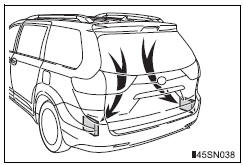
| WARNING Handling the radar sensor One Blind Spot Monitor sensor is installed inside the left and right side of the vehicle rear bumper respectively. Observe the following to ensure the Blind Spot Monitor can function correctly.
|

 The Blind Spot Monitor function
The Blind Spot Monitor function uses radar sensors to detect vehicles
that are traveling in an adjacent lane in the area that is not reflected in
the outside rear view mirror (the blind spot), and a ...
Other materials:
AUX Port/USB Port
Connect an iPod, USB memory device or portable audio player
to the AUX port/USB port as indicated below. Select “iPod”,
“USB” or “AUX” on the audio source selection screen and the
device can be operated via audio system.
Connecting using the AUX port/USB port
iPod
Open the cove ...
Problem symptoms table
HINT:
Inspect the fuse and relay before confirming the suspected
areas in the table below.
Inspect each suspected area in numerical order for the
corresponding symptom.
If the malfunction still exists after checking and confirming
that all circuits and components are normal ...
Air Mix Damper Control Servo Motor Circuit (Driver Side)
DESCRIPTION
The air mix control servo motor (air mix damper servo sub-assembly) is
controlled by the A/C amplifier.
The air mix control servo motor moves the air mix damper by rotating (normal,
reverse) with electrical
power from the A/C amplifier.
This adjusts the mix ratio of the air t ...
