Toyota Sienna Service Manual: Installation
1. INSTALL FRONT STABILIZER BAR
2. INSTALL NO. 1 FRONT STABILIZER BAR BUSHING
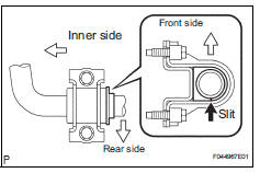
(a) Install the 2 front stabilizer bar bush No.1 to the stabilizer bar front.
NOTICE: Install the bushings with the slit facing on the rear side of the vehicle.
HINT: Install the bushing to the outer side of the bushing stopper on the stabilizer bar as shown in the illustration.
3. INSTALL EXHAUST MANIFOLD SUB-ASSEMBLY RH
HINT: (See page EM-48)
4. INSTALL MANIFOLD STAY
HINT: (See page EM-51)
5. INSTALL STEERING INTERMEDIATE SHAFT ASSEMBLY
HINT: (See page PS-21)
6. INSTALL RACK & PINION POWER STEERING GEAR ASSEMBLY
HINT: (See page PS-21)
7. CONNECT PRESSURE FEED TUBE ASSEMBLY
HINT: (See page PS-21) SST 09023-12701
8. INSTALL TIE ROD ASSEMBLY LH
HINT: (See page AH-4)
9. INSTALL TIE ROD ASSEMBLY RH
HINT: Remove the RH side by the same procedures as the LH side.
10. INSTALL NO. 1 FRONT STABILIZER BRACKET LH
(a) Install the front stabilizer bracket No.1 LH with the 2 bolts.
Torque: 17 N*m (173 kgf*cm, 12 ft.*lbf)
11. INSTALL NO. 1 FRONT STABILIZER BRACKET RH
HINT: Install the RH side by the same procedures as the LH side.
12. INSTALL CENTER EXHAUST PIPE ASSEMBLY
HINT: (See page EX-10)
13. INSTALL FRONT STABILIZER LINK ASSEMBLY LH
HINT: (See page AH-4)
14. INSTALL FRONT STABILIZER LINK ASSEMBLY RH
HINT: Install the RH side by the same procedures as the LH side.
15. INSTALL FRONT WHEELS
16. INSPECT CENTER FRONT WHEEL
17. INSPECT STEERING WHEEL CENTER POINT
18. ADD POWER STEERING FLUID
19. BLEED POWER STEERING FLUID
HINT: (See page PS-6)
20. CHECK POWER STEERING FLUID LEAKAGE
21. INSPECT AND ADJUST FRONT WHEEL ALIGNMENT
HINT: (See page SP-4)
 Inspection
1. INSPECT FRONT STABILIZER LINK ASSEMBLY LH
(a) As shown in the illustration, flip the ball joint stud
back and forth 5 times, before installing the nut.
(b) Using a torque wrench, turn the nut ...
 Rear coil spring
COMPONENTS
...
Other materials:
Open or Short Circuit in ABS Solenoid Relay Circuit
DESCRIPTION
The ABS solenoid relay is built in the brake actuator assembly. This relay
supplies power to each ABS
solenoid. If the initial check is OK, after the ignition switch is turned to the
ON position, the relay goes on.
WIRING DIAGRAM
Refer to DTCs C0226/21, C0236/22, C0246/23 ...
Sound Signal Circuit between Radio Receiver and Stereo Jack Adapter
DESCRIPTION
The stereo jack adapter sends an external device sound signal to the radio
receiver through this circuit.
The sound signal that has been sent is amplified by the stereo component
amplifier or radio receiver, and
then is sent to the speakers.
If there is an open or short in th ...
System check
HINT:
Performing a SYSTEM CHECK enables the system,
which consists of the multiple actuators, to be operated
without removing any parts. In addition, it can show
whether or not any DTCs are set, and can detect
potential malfunctions in the system. The SYSTEM
CHECK can be performed with an inte ...
