Toyota Sienna Service Manual: Problem symptoms table
HINT: Proceed to troubleshooting of each circuit in the table below.
1. HEADLIGHT AND TAIL LIGHT SYSTEM
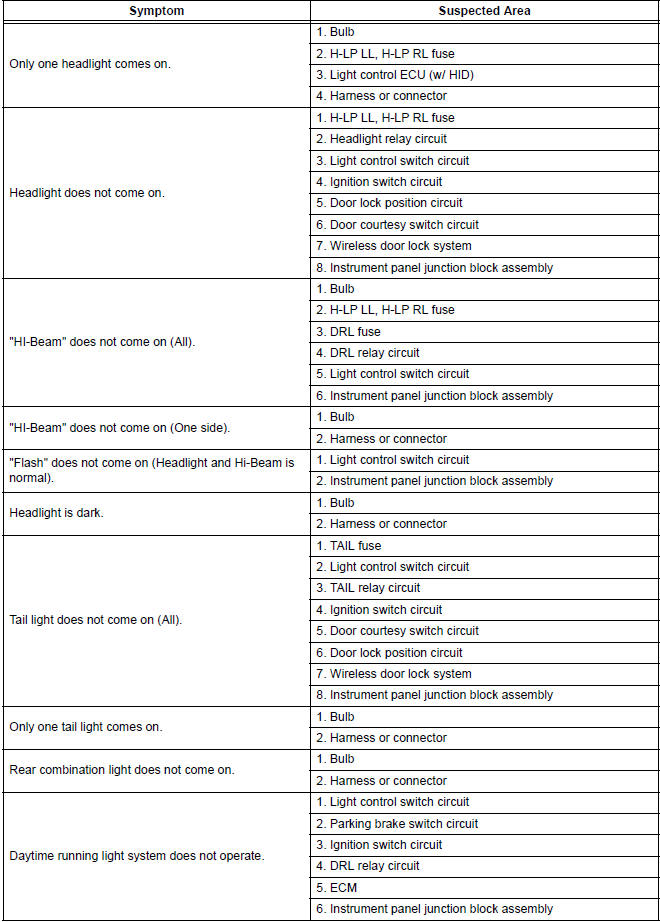
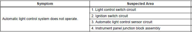
2. AUTOMATIC LIGHT CONTROL SYSTEM
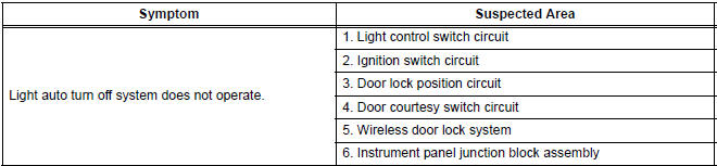
3. LIGHT AUTO TURN OFF SYSTEM
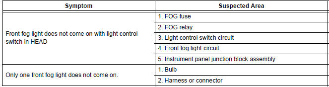
4. FOG LIGHT SYSTEM
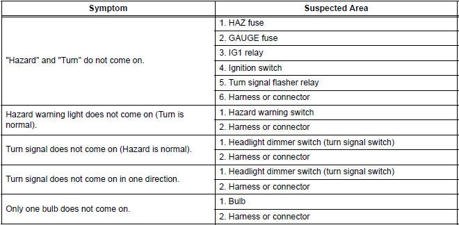
5. TURN SIGNAL AND HAZARD WARNING SYSTEM
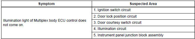
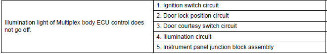
6. ILLUMINATED ENTRY SYSTEM
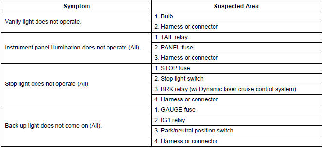
7. OTHERS
 Operation check
1. ILLUMINATED ENTRY SYSTEM OPERATION CHECK
The illuminated entry system is explained below:
Turn the ignition switch OFF, close all the doors,
and set them in the lock conditi ...
 Terminals of ECU
1. Instrument Panel Junction Block Assembly
...
Other materials:
Power Slide Door RH does not Operate When Satellite Switch is
Pressed
DESCRIPTION
The power slide door operates only when the power slide door main
switch is ON (switch free: orange
paint on the top of the switch appears). The power slide door ECU RH
controls the power slide door
RH, which activates the slide door motor to open / close the slide do ...
Diagnosis system
1. CHECK DLC3
The vehicle's ECU uses ISO 15765-4 for
communication protocol. The terminal arrangement
of the DLC3 complies with SAE J1962 and matches
the ISO 15765-4 format.
NOTICE:
*: Before measuring the resistance, leave the
vehicle as is for at least 1 minute and do not
ope ...
Abnormal Temperature Inside ID1 Tire
DESCRIPTION
Each tire pressure warning valve and transmitter measures the internal
temperature of its tire as well as
tire pressure, and transmits the information to the tire pressure warning ECU
along with the transmitter ID.
If the measured temperature is out of the specified range, t ...
