Toyota Sienna Service Manual: Radio Receiver Power Source Circuit
DESCRIPTION
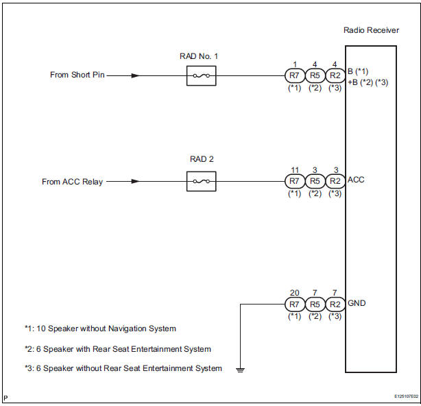
This circuit provides power to the radio receiver.
WIRING DIAGRAM
INSPECTION PROCEDURE
1 INSPECT RADIO RECEIVER ASSEMBLY
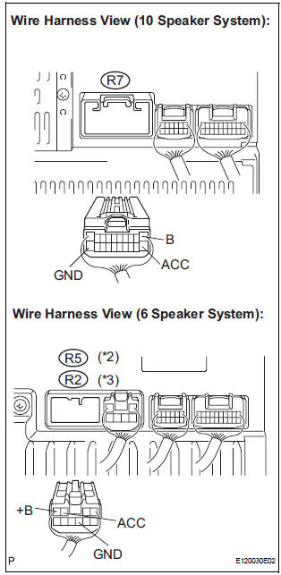
- Disconnect the radio receiver connector.
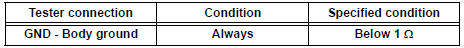
- Measure the resistance according to the value in the table below.
Standard resistance
- Measure the voltage according to the values in the table below.
Standard voltage
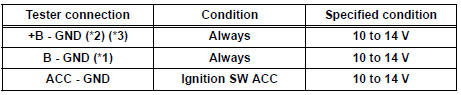
*1: 10 Speaker without Navigation System
*2: 6 Speaker with Rear Seat Entertainment System
*3: 6 Speaker without Rear Seat Entertainment System
PROCEED TO NEXT CIRCUIT INSPECTION SHOWN IN PROBLEM SYMPTOMS TABLE
 Television Display Assembly Communication Error
INSPECTION PROCEDURE
1 IDENTIFY THE COMPONENT SHOWN BY THE SUB-CODE
Enter the diagnostic mode.
Press the preset switch "3" to change to "Detailed
Information Mode" ...
 Stereo Component Amplifier Power Source Circuit
DESCRIPTION
This circuit provides power to the stereo component amplifier.
WIRING DIAGRAM
INSPECTION PROCEDURE
1 INSPECT STEREO COMPONENT AMPLIFIER
Disconnect the stereo component ampl ...
Other materials:
Drive information
Average fuel economy*1, 2
Displays the average fuel consumption since the function was
reset.*3
Tank average fuel economy*1, 2
Displays the average fuel consumption since the vehicle was refueled.
Trip average fuel economy*1, 2
Displays the average fuel consumption since the engine wa ...
Speaker Circuit
DESCRIPTION
The sound signal that has been amplified by the stereo component amplifier is
sent to the speakers from
the stereo component amplifier through this circuit.
If there is a short in this circuit, the stereo component amplifier detects it
and stops output to the speakers.
Thus s ...
Manual headlight leveling dial (vehicles with discharge headlights)
The level of the headlight aim can be adjusted according to the number
of passengers and the loading condition of the vehicle.
Raises the level of the headlights
Lowers the level of the headlights
Guide to dial settings
Daytime running light system (if equipped)
Bulb type: To ...
