Toyota Sienna Service Manual: Installation
1. INSTALL NAVIGATION ANTENNA ASSEMBLY
2. INSTALL INSTRUMENT PANEL SAFETY PAD SUBASSEMBLY
- Using a torque wrench, install the bolt <B>.
Torque: 20 N*m (204 kgf*cm, 14 ft.*lbf)
3. INSTALL SHIFT LEVER ASSEMBLY
- Using a torque wrench, install the 4 bolts.
Torque: 21 N*m (214 kgf*cm, 12.6 ft.*lbf)
4. INSTALL DEFROSTER NOZZLE OPENING PLATE NO.1
5. INSTALL FRONT NO.2 SPEAKER ASSEMBLY
6. INSTALL FRONT NO.1 SPEAKER ASSEMBLY
7. INSTALL INSTRUMENT PANEL SPEAKER PANEL SUB-ASSEMBLY NO.2
8. INSTALL INSTRUMENT PANEL SPEAKER PANEL SUB-ASSEMBLY
9. INSTALL FRONT PILLAR GARNISH RH
10. INSTALL FRONT PILLAR GARNISH LH
11. INSTALL INTEGRATION CONTROL & PANEL ASSEMBLY
12. INSTALL NAVIGATION RECEIVER ASSEMBLY
13. INSTALL STEREO COMPONENT SPEAKER ASSEMBLY
14. INSTALL INSTRUMENT CLUSTER FINISH PANEL GARNISH
15. INSTALL INSTRUMENT CLUSTER FINISH PANEL SUB-ASSEMBLY LOWER CENTER
16. INSTALL INSTRUMENT CLUSTER FINISH PANEL ASSEMBLY CENTER
17. INSTALL FLOOR SHIFT POSITION INDICATOR HOUSING ASSEMBLY
18. INSTALL SHIFT LEVER KNOB SUB-ASSEMBLY
19. INSTALL INSTRUMENT CLUSTER FINISH PANEL CENTER NO.2
20. INSTALL INSTRUMENT CLUSTER FINISH PANEL CENTER NO.1
21. INSTALL FLOOR CARPET COVER CENTER RH
22. INSTALL FLOOR CARPET COVER CENTER LH
23. INSTALL INSTRUMENT PANEL REGISTER ASSEMBLY NO.3
24. INSTALL INSTRUMENT PANEL REGISTER ASSEMBLY NO.1
25. INSTALL INSTRUMENT SIDE PANEL RH
26. INSTALL INSTRUMENT SIDE PANEL LH
27. INSTALL INSTRUMENT PANEL BOX NO.2
28. INSTALL GLOVE COMPARTMENT DOOR ASSEMBLY
29. INSTALL GLOVE COMPARTMENT DOOR STOPPER SUB-ASSEMBLY
30. INSTALL INSTRUMENT PANEL SAFETY PAD INSERT SUB-ASSEMBLY NO.1
31. INSTALL INSTRUMENT PANEL FINISH PANEL SUBASSEMBLY LOWER LH
32. INSTALL COWL SIDE TRIM BOARD RH
33. INSTALL COWL SIDE TRIM BOARD LH
34. INSTALL FRONT DOOR SCUFF PLATE RH
35. INSTALL FRONT DOOR SCUFF PLATE LH
36. INSTALL COMBINATION METER ASSEMBLY
37. INSTALL INSTRUMENT CLUSTER FINISH PANEL SUB-ASSEMBLY
38. INSTALL WINDSHIELD WIPER SWITCH ASSEMBLY
39. INSTALL HEADLIGHT DIMMER SWITCH ASSEMBLY
40. INSTALL SPIRAL CABLE SUB-ASSEMBLY
41. INSTALL STEERING COLUMN COVER
42. ADJUST SPIRAL CABLE SUB-ASSEMBLY
43. INSTALL STEERING WHEEL ASSEMBLY
44. INSTALL HORN BUTTON ASSEMBLY
45. INSTALL STEERING WHEEL COVER LOWER NO.2
46. INSTALL STEERING WHEEL COVER LOWER NO.3
47. CONNECT BATTERY NEGATIVE TERMINAL
48. INSPECT HORN BUTTON ASSEMBLY
49. INSPECT SRS WARNING LIGHT
 Removal
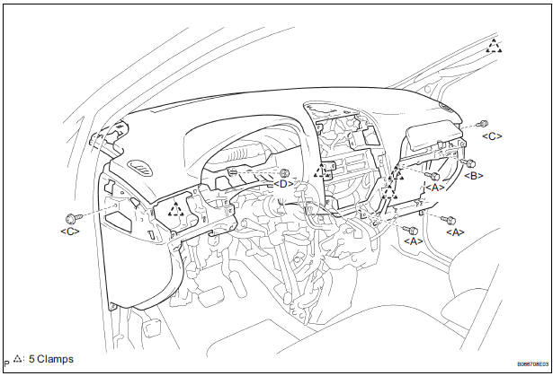
1. BOLT, SCREW AND NUT TABLE
The bolts, the screws and the nuts, which are
necessary for installation and removal of the
instrument panel are shown in the illustration below
with alpha ...

Other materials:
ACIS Control Circuit
DESCRIPTION
This circuit opens and closes the Intake Air Control Valve (IACV) in response
to changes in the engine
load in order to increase the intake efficiency (ACIS: Acoustic Control
Induction System).
When the engine speed is between 0 and 4450 rpm and the throttle valve opening
angl ...
Initialization
1. RESET
Reset the power slide door system:
The power slide door ECU records the fully open
position of the power slide door in its memory and
the power slide door fully opens and closes based
on this memory. The power slide door cannot
operate without this memory. In the case wh ...
Pressing Power Switch does not Turn on System
INSPECTION PROCEDURE
1 CHECK VEHICLE CONDITION
Check that conditions in the cabin are not likely to cause
condensation.
HINT:
This problem occurs when the cabin is humid and the
temperature changes rapidly. This may produce
condensation, resulting in a short circuit.
OK:
Condensation ...
