Toyota Sienna Service Manual: Rear combination light assembly
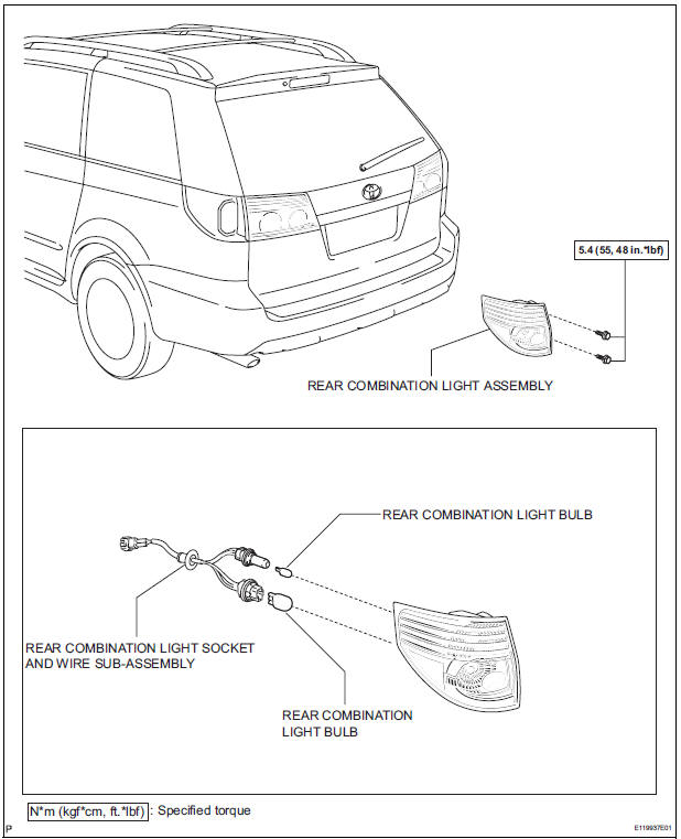
COMPONENTS
REMOVAL
1. DISCONNECT CABLE FROM NEGATIVE BATTERY TERMINAL
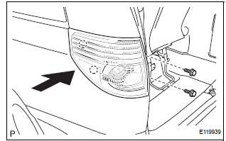
2. REMOVE REAR COMBINATION LIGHT ASSEMBLY
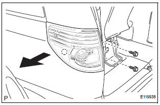
- Remove the 2 bolts.
- Disengage the 2 pins and separate the rear combination light assembly as shown in the illustration.
- Disconnect the connector and remove the rear combination light assembly.
DISASSEMBLY
1. REMOVE REAR COMBINATION LIGHT BULB
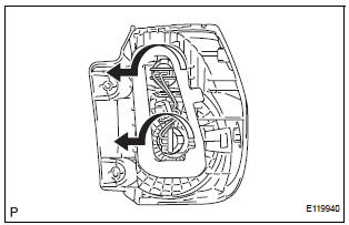
- Turn in the direction indicated by the arrow and separate the 2 rear combination light bulbs.
- Remove the 2 rear combination light bulbs from the rear combination light socket and wire subassembly.
REASSEMBLY
1. INSTALL REAR COMBINATION LIGHT BULB
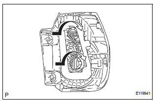
- Install the 2 rear combination light bulbs to the rear combination light socket and wire sub-assembly.
- Turn in the direction indicated by the arrow and install the 2 rear combination light bulbs to the rear combination light assembly.
INSTALLATION
1. INSTALL REAR COMBINATION LIGHT ASSEMBLY
- Connect the connector.
- Install the rear combination light assembly with the 2
bolts and 2 pins as shown in the illustration.
Torque: 5.4 N*m (55 kgf*cm, 48 in.*lbf)
2. CONNECT CABLE TO NEGATIVE BATTERY TERMINAL
 Installation
1. INSTALL FOG LIGHT ASSEMBLY
Install the fog light assembly with the 2 claws and 2
pins.
2. INSTALL FRONT BUMPER ASSEMBLY
3. CONNECT CABLE TO NEGATIVE BATTERY
TERMINAL
4. VEHICL ...
 Back-up light assembly
COMPONENTS
REMOVAL
1. REMOVE BACK DOOR GARNISH CENTER
2. REMOVE BACK DOOR SIDE GARNISH LH
3. REMOVE BACK DOOR SIDE GARNISH RH
4. REMOVE BACK DOOR STRAP COVER SUBASSEMBLY
5. REMOVE BACK D ...
Other materials:
Installation
1. INSTALL HEATED OXYGEN SENSOR (for Bank 2
Sensor 2) (See page EC-39)
2. INSTALL FRONT EXHAUST PIPE ASSEMBLY
(a) Install a new gasket to the front exhaust pipe
assembly.
(b) Install the front exhaust pipe assembly with the 2
nuts.
Torque: 62 N*m (632 kgf*cm, 46 ft.*lbf)
3. V
V(A) ins ...
Adjustment
HINT:
On the RH side, use the same procedures as on the LH side.
1. INSPECT SLIDE DOOR PANEL SUB-ASSEMBLY LH
Check that the clearance is within the standard
range.
Standard
2. ADJUST SLIDE DOOR PANEL SUB-ASSEMBLY LH
Using the SST, horizontally and vertically adjust the
...
VIN not Programmed or Mismatch - ECM / PCM
DTC P0630 VIN not Programmed or Mismatch - ECM / PCM
DESCRIPTION
DTC P0630 is set when the Vehicle Identification Number (VIN) is not stored
in the Engine Control Module
(ECM) or the input VIN is not accurate. Input the VIN with the intelligent
tester.
MONITOR STRATEGY
TYPICAL ENABL ...
