Toyota Sienna Service Manual: Rear Power Seat Switch Circuit
DESCRIPTION
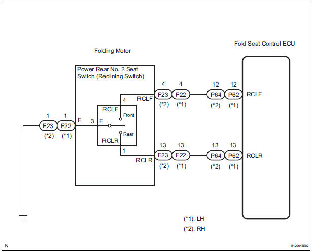
When the power rear no. 2 seat switch is operated, a recline signal is sent to the fold seat control ECU.
The ECU activates the reclining motor based on the signal from the power rear no. 2 seat switch.
WIRING DIAGRAM
INSPECTION PROCEDURE
1 INSPECT FOLD SEAT CONTROL ECU
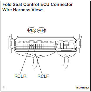
- Remove the fold seat control ECU.
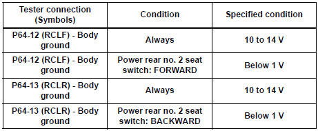
- Measure the voltage according to the value(s) in the table below.
Standard voltage: LH side
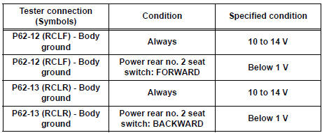
RH side
2 CHECK HARNESS AND CONNECTOR (FOLD SEAT CONTROL ECU - FOLDING MOTOR)
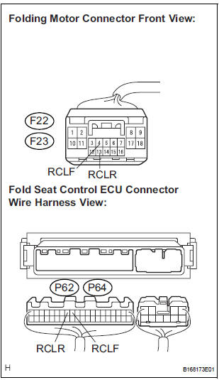
- Disconnect the connectors from the fold seat control ECU.
- Disconnect the connector from the folding motor.
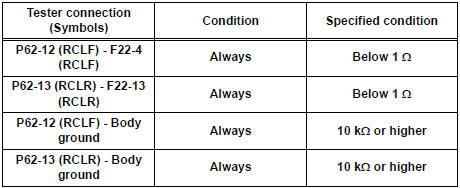
- Measure the resistance according to the value(s) in the table below.
Standard resistance: LH side
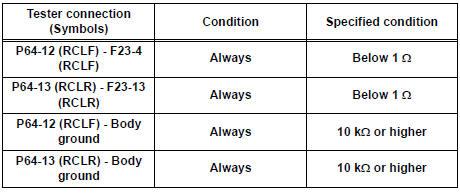
RH side
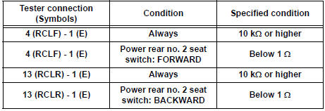
3 INSPECT POWER REAR NO. 2 SEAT SWITCH
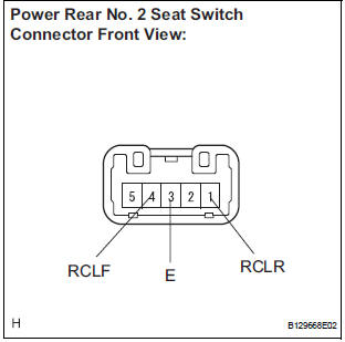
- Disconnect the connector from the power rear no. 2 seat switch.
- Measure the resistance according to the value(s) in the table below.
Standard resistance: LH side
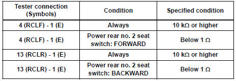
RH side
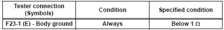
4 CHECK HARNESS AND CONNECTOR (FOLDING MOTOR - BODY GROUND)
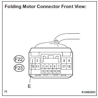
- Measure the resistance according to the value(s) in the table below.
Standard resistance: LH side
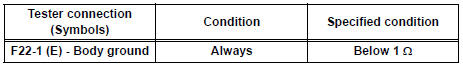
RH side
5 REPAIR OR REPLACE HARNESS OR CONNECTOR (WIRE INSIDE SEAT)
- Repair or replace harness or connector (wire inside seat) and check that the malfunction disappears.
OK: Malfunction disappears.
END
 Lock Switch Circuit
DESCRIPTION
Each of the left and right seats has lock switches that detect the lock
condition of the seat legs to the floor
when the seat is in the original or folded-down state. If any of the loc ...
 Fold Lock Switch Circuit
DESCRIPTION
Each of the left and right seats has a fold lock switch that detects the lock
condition of the seat legs and
floor when the seat is in the stowed state. If the fold lock switch detects ...
Other materials:
Removal
1. REMOVE REAR WHEEL
2. REMOVE REAR SHOCK ABSORBER CAP LH
(a) Remove the shock absorber head cover.
(b) Remove the shock absorber cap LH.
3. REMOVE SHOCK ABSORBER ASSEMBLY REAR LH
(a) Support the rear axle beam with a jack.
(b) Using a 6 mm hexagon wrench to hold the piston
rod, ...
2Gr-fe engine mechanical
SERVICE DATA
TORQUE SPECIFICATIONS
2GR-FE FUEL
SERVICE DATA
TORQUE SPECIFICATIONS
2GR-FE EMISSION CONTROL
SERVICE DATA
TORQUE SPECIFICATIONS
2GR-FE INTAKE
SERVICE DATA
TORQUE SPECIFICATIONS
2GR-FE EXHAUST
SERVICE DATA
TORQUE SPECIFICAT ...
Reassembly
1. INSTALL NO. 1 COOLER THERMISTOR
(a) Install the No. 1 cooler thermistor as shown in the
illustration.
NOTICE:
Be sure to insert the thermistor only once
because reinserting it will not allow it to be
firmly secured.
When reusing the evaporator, insert the
thermistor one row ne ...
