Toyota Sienna Service Manual: Adjustment
HINT: On the RH side, use the same procedures as on the LH side.
1. INSPECT SLIDE DOOR PANEL SUB-ASSEMBLY LH
- Check that the clearance is within the standard range.
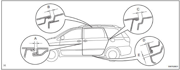
Standard

2. ADJUST SLIDE DOOR PANEL SUB-ASSEMBLY LH
- Using the SST, horizontally and vertically adjust the
door by loosening the hinge center bolts.
SST 09812-00010, 09812-00020
- Tighten the hinge assembly center bolts after the
adjustment.
Torque: 31 N*m (306 kgf*cm, 23 ft.*lbf)
- Vertically adjust the front side of the door by loosening the roller lower bolts.
- Tighten the roller lower bolts after the adjustment.
Torque: 31 N*m (306 kgf*cm, 23 ft.*lbf)
- Horizontally adjust the front lower side of the door by loosening the roller lower bolts.
- Tighten the roller lower bolts after the adjustment.
Torque: 31 N*m (306 kgf*cm, 23 ft.*lbf)
- Horizontally adjust the front upper side of the door by loosening the roller upper bolts.
- Tighten the roller assembly lower bolts after the
adjustment.
Torque: 8.5 N*m (82 kgf*cm, 73 in.*lbf)
- Adjust the position of the door lock striker by slightly loosening the striker mounting screws and hitting the striker with a plastic-faced hammer.
- Tighten the striker mounting screws after the
adjustment.
Torque: 23 N*m (235 kgf*cm, 17 ft.*lbf)
- Adjust the position of the front lock striker by slightly loosening the striker mounting screws and hitting the striker with a plastic-faced hammer.
- Tighten the striker mounting screws after the
adjustment.
Torque: 23 N*m (235 kgf*cm, 17 ft.*lbf)
- Adjust the position of the down stopper by moving the male stopper, so that the male stopper can enter smoothly.
- Tighten the female stopper mounting bolts after the
adjustment.
Torque: 5.5 N*m (58 kgf*cm, 49 in.*lbf)
 Disassembly
HINT:
On the RH side, use the same procedures as on the LH side.
1. REMOVE REAR DOOR WINDOW FRAME MOULDING
REAR LH (See page ET-30)
2. REMOVE REAR DOOR WINDOW FRAME MOULDING
SUB-ASSEMBLY LH (See ...
 Reassembly
1. INSTALL REAR DOOR WIRE SUB-ASSEMBLY LH
Install the wire.
NOTICE:
When installing the wire, push the areas where
the clips are installed in order to prevent
damage and deformation.
...
Other materials:
Installation
1. INSTALL VVT SENSOR (for Bank 2 Exhaust Side)
Install the VVT sensor with the bolt.
Torque: 10 N*m (102 kgf*cm, 7 ft.*lbf)
Connect the VVT sensor connector.
2. INSTALL VVT SENSOR (for Bank 2 Intake Side)
Install the VVT sensor with the bolt.
Torque: 10 N* ...
Black Screen
INSPECTION PROCEDURE
1 CHECK DISPLAY SETTING
Check that the display is not in "Screen OFF" mode.
OK:
The display setting is not in "Screen OFF" mode.
2 CHECK IMAGE QUALITY SETTING
Check that the screen color quality can be set.
OK:
Setting is possible.
PRESS PA ...
Removal
1. DISCONNECT CABLE FROM NEGATIVE BATTERY
TERMINAL
2. REMOVE V-BANK COVER SUB-ASSEMBLY (See
page EM-28)
3. REMOVE PURGE VSV
(a) Disconnect the purge VSV connector.
(b) Disconnect the 2 purge line hoses from the purge
VSV.
(c) Remove the purge VSV from the air cleaner hose.
(d) R ...
