Toyota Sienna Service Manual: Installation
1. INSTALL REAR DIFFERENTIAL DRIVE PINION BEARING SPACER
(a) Install a new bearing spacer.
2. INSTALL REAR DRIVE PINION FRONT TAPERED ROLLER BEARING
(a) Install the tapered roller bearing.
3. INSTALL REAR DIFFERENTIAL DRIVE PINION OIL SLINGER
(a) Install the oil slinger, as shown in the illustration.
4. INSTALL REAR DIFFERENTIAL CARRIER OIL SEAL
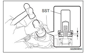
(a) Using SST and a hammer, install a new oil seal.
SST 09554-22010 Oil seal drive in depth: 2.0 +- 0.3 mm (0.079 +- 0.012 in.)
(b) Coat MP grease to the oil seal lip.
5. INSTALL REAR DRIVE PINION COMPANION FLANGE SUB-ASSEMBLY
(a) Using SST, install the companion flange on the shaft.
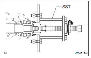
SST 09950-30012 (09951-03010, 09953-03010, 09954-03010, 09955-03030, 09956-03020)
NOTICE: Apply hypoid gear oil to the SST center bolt tip and threads before use.
6. INSTALL REAR DRIVE PINION NUT
(a) Coat the threads of a new nut with hypoid gear oil LSD.
(b) Using SST to hold the flange, torque the nut.
SST 09330-00021 Torque: 108 N*m (1,100 kgf*cm, 80 ft.*lbf)
7. INSPECT DIFFERENTIAL DRIVE PINION PRELOAD
(a) Inspect differential drive pinion preload (See page DF-31).
(b) Using a chisel and a hammer, stake the drive pinion nut.
8. INSTALL REAR DIFFERENTIAL DRAIN PLUG
(a) Using a hexagon wrench (10 mm), install the filler plug with a new gasket.
Torque: 49 N*m (500 kgf*cm, 36 ft.*lbf)
9. ADD DIFFERENTIAL OIL
(a) Fill the rear differential carrier assembly with hypoid gear oil.
10. INSPECT DIFFERENTIAL OIL
HINT: (See page DF-3)
11. INSTALL REAR DIFFERENTIAL FILLER PLUG
(a) Using a hexagon wrench (10 mm), install the filler plug with a new gasket.
Torque: 49 N*m (500 kgf*cm, 36 ft.*lbf)
12. INSTALL PROPELLER WITH CENTER BEARING SHAFT ASSEMBLY
(a) Install propeller with center bearing shaft assembly (See page PR-9).
(b) Fully tighten propeller with center bearing shaft assembly (See page PR-10).
13. INSTALL EXHAUST PIPE ASSEMBLY
HINT: (See page EX-10)
14. INSPECT FOR EXHAUST GAS LEAK
HINT: (See page EX-12)
 Removal
1. REMOVE FRONT EXHAUST PIPE ASSEMBLY
HINT:
(See page EX-8)
2. REMOVE PROPELLER WITH CENTER BEARING
SHAFT ASSEMBLY
HINT:
(See page PR-3)
3. REMOVE REAR DIFFERENTIAL FILLER PLUG
(a) Using a hex ...
 Rear differential carrier assembly
Components
...
Other materials:
Engine compartment
Items
Check points
Battery
Check connections
Brake fluid
Is the brake fluid at the correct level?
Engine coolant
Is the engine coolant at the correct
level?
Engine oil
Is the engine oil at the correct level?
Exhaust system ...
Location of the spare tire, jack and tools
Spare tire
Jack handle
Tire bag
Jack
Wheel nut wrench
Adapter socket
Tire strap
WARNINGUsing the tire jack
Observe the following precautions.
Improper use of the tire jack may cause the vehicle to suddenly fall off
the jack, leading to death or serious injury. ...
Closing the fuel tank cap
After refueling, turn the fuel tank
cap until you hear a click. Once
the cap is released, it will turn
slightly in the opposite direction.
WARNINGWhen replacing the fuel tank cap
Do not use anything but a genuine Toyota fuel tank cap designed for
your
vehicle. Doing so may c ...
