Toyota Sienna Service Manual: Diagnosis system
1. CHECK DLC3
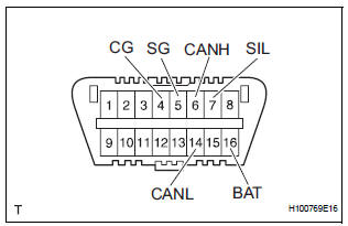
- The ECU uses the ISO 15765-4 for communication protocol. The terminal arrangement of the DLC3 complies with SAE J1962 and matches the ISO 15765-4 format.

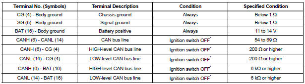
NOTICE: *: Before measuring the resistance, leave the vehicle as is for at least 1 minute and do not operate the ignition switch, any other switches, or the doors.
If the result is not as specified, the DLC3 may have a malfunction. Repair or replace the harness and connector.
- Connect the cable of the intelligent tester to the DLC3, turn the ignition switch to the ON position, and attempt to use the tester. If the display indicates that a communication error has occurred, there is a problem either with the vehicle or with the tester.
- If communication is normal when the tester is connected to another vehicle, inspect the DLC3 of the original vehicle.
- If communication is still not possible when the tester is connected to another vehicle, the problem may be in the tester itself. Consult the Service Department listed in the tester's instruction manual.
2. CHECK INDICATOR
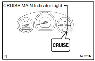
- Turn the ignition switch to the ON position.
- Check that the CRUISE main indicator light illuminates when the cruise control main switch is turned on, and that the indicator light turns off when the main switch is turned off. If the results are not as specified, inspect the CRUISE main indicator light circuit.
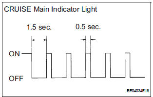
HINT: While driving with cruise control, the ECM activates AUTO CANCEL of the cruise control system when a malfunction occurs in one of the following: vehicle speed sensors, stop light switch, or other related parts. When AUTO CANCEL is activated, the CRUISE main indicator light outputs the blinking pattern as shown in the illustration. At the same time, data of the malfunction is stored as a DTC
 Terminals of ECM
1. CHECK ECM
...
 DTC check / clear
1. DTC CHECK
Connect the intelligent tester to the DLC3.
Connect the intelligent tester to the Controller
Area Network Vehicle Interface Module (CAN
VIM). Then connect th ...
Other materials:
Rear speaker
COMPONENTS
ON-VEHICLE INSPECTION
1. INSPECT REAR SPEAKER
HINT:
Remove interior parts so that the rear speaker can be
seen.
Check the speaker installation.
OK:
The speaker is securely installed.
If the result is not as specified, reinstall the rear
speaker.
Vi ...
Noise Occurs from Generator while Engine is Running
INSPECTION PROCEDURE
1 CHECK LOOSENESS OF V-RIBBED BELT
(a) Check the tension of the belt by pushing it down with a
finger.
OK:
The tension of the belt is enough.
2 CHECK V-RIBBED BELT FOR WEAR
(a) Check the V-ribbed belt for wear.
OK:
The V-ribbed belt is not worn.
3 CHECK CLUTC ...
Installation
1. INSTALL ENGINE OIL COOLER
(a) Clean the oil cooler contact surface on the cooler
mounting.
(b) Install a new O-ring to the oil cooler.
(c) Install the oil cooler assembly with the union bolt.
Torque: 68 N*m (693 kgf*cm, 50 ft.*lbf)
Install the 2 water by-pass hoses with the bolt ...
