
Toyota Sienna Service Manual: Reassembly
1. INSTALL NO. 1 SEAT CUSHION FRAME SUBASSEMBLY
- Install the seat cushion frame with the bolt.
Torque: 20.6 N*m (210 kgf*cm, 15 ft.*lbf)
2. INSTALL RECLINING CONTROL LINK SUBASSEMBLY
- Install the reclining control link with the E-ring.
- Install the nut.
3. INSTALL REAR SEAT TRACK ADJUSTING HANDLE
- Install the seat track adjusting handle.
4. INSTALL REAR SEAT RECLINING ADJUSTER ASSEMBLY RH
- Install the seat reclining adjuster with the bolt.
Torque: 55 N*m (561 kgf*cm, 41 ft.*lbf)
5. INSTALL NO. 1 REAR SEAT BELT ASSEMBLY OUTER RH
- Install the reclining sensor together with the seat
belt with the nut.
Torque: 4.0 N*m (41 kgf*cm, 35 in.*lbf)
6. INSTALL RECLINING CONNECTING PIPE
7. INSTALL REAR SEAT RECLINING ADJUSTER ASSEMBLY LH
- Install the seat reclining adjuster with the bolt.
Torque: 43.1 N*m (439 kgf*cm, 32 ft.*lbf)
- Install the reclining remote control cable.
8. INSTALL REAR SEAT HINGE COVER
- Install the seat hinge cover with the screw.
9. INSTALL REAR SEAT HINGE COVER LH
- Install the seat hinge cover with the screw.
10. INSTALL NO. 1 SEATBACK FRAME SUB-ASSEMBLY
- Install the seatback frame with the bolt.
Torque: for RH side 55 N*m (561 kgf*cm, 41 ft.*lbf)
for LH side 43.1 N*m (439 kgf*cm, 32 ft.*lbf) - Install the seat belt retractor with the nut.
Torque: 42 N*m (428 kgf*cm, 31 ft.*lbf)
11. INSTALL REAR SEAT SHOULDER BELT COVER RH
- Install the seat shoulder belt cover with the 2 screws.
12. INSTALL NO. 1 SEAT CUSHION COVER SUBASSEMBLY
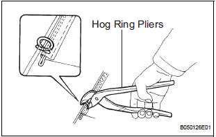
- Install the seat cushion pad to the seat cushion cover.
- Using hog ring pliers, install the seat cushion cover to the seat cushion pad with new hog rings.
NOTICE:
- Be careful not to damage the cover.
- hen installing the hog rings, take care to prevent wrinkles as much as possible.
13. INSTALL REAR SEATBACK COVER
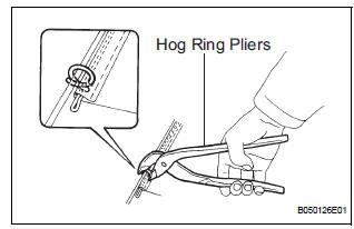
- Install the seatback pad.
- Using hog ring pliers, install the seatback cover completely with new hog rings.
NOTICE:
- Be careful not to damage the cover.
- When installing the hog rings, take care to prevent wrinkles as much as possible.
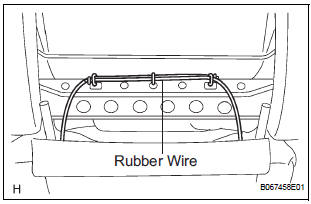
- Attach a rubber wire with new hog rings, as shown in the illustration.
- Using hog ring pliers, install new hog rings.
NOTICE:
- Be careful not to damage the cover.
- When installing the hog rings, take care to prevent wrinkles as much as possible.
- Install the 2 headrest supports.
14. INSTALL REAR SEATBACK LOCK BEZEL UPPER
- Install the rear seatback lock bezel upper.
- Install the clip and screw.
15. INSTALL REAR SEATBACK BOARD
- Install the seatback board with the 2 screws.
- Install the rear seatback board cap.
16. INSTALL FOLD SEAT STOPPER BAND ASSEMBLY
- Install the fold seat stopper band with the screw.
17. INSTALL REAR SEAT LAP TYPE BELT ASSEMBLY CENTER
- Install the lap type belt with the bolt.
Torque: 42 N*m (428 kgf*cm, 31 ft.*lbf)
18. INSTALL RECLINING ADJUSTER COVER RH
- Install the reclining adjuster cover.
- Install the 3 screws.
19. INSTALL RECLINING ADJUSTER INSIDE COVER LH
- Install the reclining adjuster inside cover.
- Install the 3 screws.
20. INSTALL RH SEAT REAR SEAT LOCK COVER
- Install the seat lock cover with the screws.
21. INSTALL LH SEAT REAR SEAT LOCK COVER
- Install the LH seat rear seat lock cove with the 2 screws.
22. INSTALL REAR SEAT LEG SIDE COVER LH
- Install the rear seat leg side cover with the 2 screws.
23. INSTALL REAR SEAT LEG COVER RH
- Install the rear seat leg cover RH with the 2 screws.
24. INSTALL REAR SEAT LEG COVER LH
- Install the rear seat leg cover LH with the 2 screws.
 Disassembly
1. REMOVE REAR SEAT LEG COVER LH
Remove the 2 screws and seat leg cover.
2. REMOVE REAR SEAT LEG COVER RH
Remove the 2 screws and seat leg cover.
3. REMOVE REAR SEAT LEG SIDE ...
 Installation
1. INSTALL REAR NO. 1 SEAT ASSEMBLY CENTER
Place the seat in the cabin.
NOTICE:
Be careful not to damage the body.
Install the rear seat.
Install the seat belt anchor p ...
Other materials:
On-vehicle inspection
1. Inspect intake air surge tank assembly
(A) inspection procedure when applying voltage
between the terminals:
(1) Disconnect the connector from the intake air
control valve.
(2) Apply battery voltage between terminals 1 (-)
and 2 (+) of the intake air control valve. Check
that a click ...
Description of code registration
It is necessary to register the transmitter ID in the tire
pressure warning ECU when replacing the tire pressure
warning valve and transmitter and/or tire pressure
warning ECU.
(a) Before registration
(1) In case of tire pressure warning ECU
replacement.
Read the registered transmitter I ...
Operation check
1. ILLUMINATED ENTRY SYSTEM OPERATION CHECK
The illuminated entry system is explained below:
Turn the ignition switch OFF, close all the doors,
and set them in the lock condition.
Unlock any door and open any other doors and
check that the room light comes on. Close ...
