Toyota Sienna Service Manual: Reassembly
1. INSTALL PLANETARY GEAR
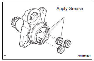
(a) Apply grease to the planetary gears and pin parts of the planetary shaft.
(b) Install the 3 planetary gears.
2. INSTALL STARTER ARMATURE ASSEMBLY
(a) Apply grease to the plate washer and the armature shaft.
(b) Install the starter armature to the starter commutator end frame.
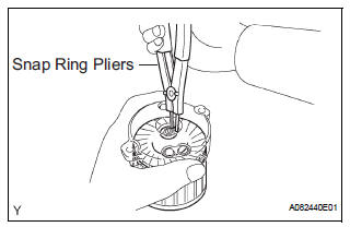
(c) Using snap ring pliers, install the plate washer and a new snap ring.
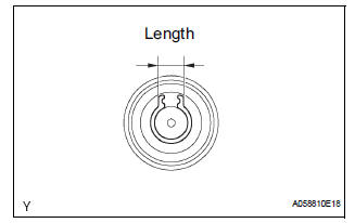
(d) Using a vernier caliper, measure length of the snap ring.
Maximum length: 5.0 mm (0.197 in.) If the length is greater than the maximum, replace it with a new snap ring
3. INSTALL DRIVE HOUSING STARTER BEARING COVER
(a) Install the drive housing starter bearing cover to the starter commutator end frame.
4. INSTALL STARTER ARMATURE PLATE
(a) Insert the starter armature plate to the starter yoke.
(b) Align the keyway of the starter plate with the key inside the starter yoke, and install the starter plate.
5. INSTALL STARTER COMMUTATOR END FRAME ASSEMBLY
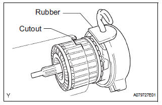
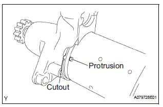
(a) Align the rubber with the convex cutout of starter yoke.
(b) Install starter commutator end frame to the starter yoke.
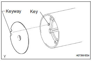
6. INSTALL STARTER YOKE ASSEMBLY
(a) Align the key of the starter yoke with the keyway of repair service starter kit.
(b) Install the starter yoke with the 2 through bolts.
Torque: 6.0 N*m (61 kgf*cm, 53 in.*lbf)
7. INSTALL REPAIR SERVICE STARTER KIT
(a) Apply grease to the plunger and the hook.
(b) Hang the plunger hook of the repair service starter kit to the drive lever.
(c) Install the plunger and return spring.
(d) Install the repair service starter kit with the 2 screws.
Torque: 7.5 N*m (76 kgf*cm, 66 in.*lbf)
(e) Connect the lead wire to the repair service starter kit with the nut.
Torque: 10 N*m (102 kgf*cm, 7 ft.*lbf)
 Inspection
1. Inspect starter assembly
NOTICE:
These tests must be performed within 3 to 5 seconds
to avoid burning out the coil.
(a) Perform the pull-in test.
(1) Disconnect the lead ...
 Installation
1. INSTALL STARTER ASSEMBLY
(a) Install the starter with the 2 bolts.
Torque: 37 N*m (380 kgf*cm, 26 ft.*lbf) for bolt
(b) Connect the starter connector.
(c) Install the terminal nut a ...
Other materials:
Removal
1. Disconnect battery negative terminal
2. Remove instrument cluster finish panel
sub-assembly center
Hint:
(see page ip-9)
3. Remove transmission control cable assembly
(a) Remove the nut from the control shaft lever.
(b) Disconnect the transmission control cable assembly
from the con ...
Low Battery Positive Voltage
DTC C1241/41 Low Battery Positive Voltage
DESCRIPTION
WIRING DIAGRAM
INSPECTION PROCEDURE
1 INSPECT ECU-IG FUSE
(a) Remove the ECU-IG fuse from the driver side J/B.
(b) Check continuity of the ECU-IG fuse.
Standard resistance
2 CHECK BATTERY
(a) Check the positive battery volt ...
Tire Pressure Warning Light Circuit
DESCRIPTION
If the ECU detects trouble, the tire pressure warning light blinks (comes on
after blinking for 1 minute) and
tire pressure monitor is cancelled at the same time. At this time, the ECU
records a DTC in the memory.
Connect terminals TC and CG of DLC3 to make the tire pressure war ...
