Toyota Sienna Service Manual: Installation
1. INSTALL STARTER ASSEMBLY
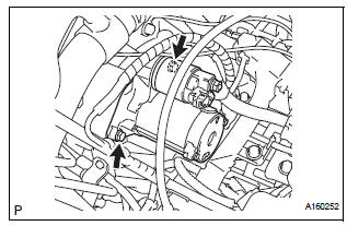
(a) Install the starter with the 2 bolts.
Torque: 37 N*m (380 kgf*cm, 26 ft.*lbf) for bolt
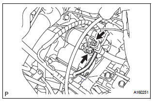
(b) Connect the starter connector.
(c) Install the terminal nut and cover the nut with the cap.
Torque: 9.8 N*m (100 kgf*cm, 7 ft.*lbf) for nut
2. INSTALL NO. 1 AIR CLEANER INLET
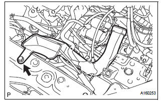
(a) Install the No. 1 air cleaner inlet with the bolt.
Torque: 5.0 N*m (51 kgf*cm, 44 in.*lbf)
3. INSTALL AIR CLEANER BRACKET
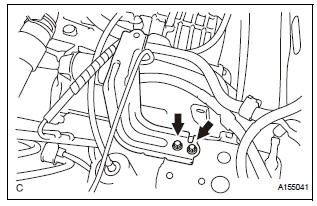
(a) Remove the 2 bolts and air cleaner bracket.
Torque: 7.8 N*m (80 kgf*cm, 69 in.*lbf)
4. INSTALL AIR CLEANER CASE SUB-ASSEMBLY (See page EM-59) 5. INSTALL AIR CLEANER FILTER ELEMENT (See page EM-59) 6. INSTALL AIR CLEANER CAP SUB-ASSEMBLY (See page FU-20) 7. INSTALL NO. 2 AIR CLEANER INLET (See page EM- 60) 8. INSTALL BATTERY (See page EM-59)
 Reassembly
1. INSTALL PLANETARY GEAR
(a) Apply grease to the planetary gears and pin parts of
the planetary shaft.
(b) Install the 3 planetary gears.
2. INSTALL STARTER ARMATURE ASSEMBLY
(a) Apply ...
 Starter relay
On-vehicle inspection
1. Inspect starter relay
(a) Using an ohmmeter, measure the resistance
between each terminal.
Standard resistance
If the result is not as specified, replace the starter ...
Other materials:
System description
1. GENERAL
In conjunction with impact absorbing structure for a
frontal collision, the SRS (Supplemental Restraint
System) driver airbag and front passenger airbag
were designed to supplement seat belts in the event
of a frontal collision in order to help reduce shock to
the head ...
Only Back Door cannot be Opened
DESCRIPTION
With power back door: The signal for manual locking/unlocking operation of
the driver/passenger side
door and the signal for locking/unlocking operation interlocked with the driver
side door key cylinder are
sent to the back door ECU from the body ECU using the MPX line. In respon ...
Air Outlet Damper Control Servo Motor Circuit
DESCRIPTION
This circuit turns the servo motor and changes each damper position by
receiving the signals from the A/
C amplifier.
The air outlet damper servo motor switches the air outlet mode by rotating
(normal, reverse) with electrical
power from the A/C amplifier.
When the AUTO swit ...
