Toyota Sienna Service Manual: Reassembly
1. BEARING POSITION
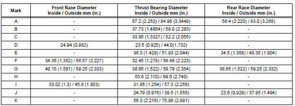
2. INSTALL DIFFERENTIAL GEAR LUBE APPLY TUBE
(a) Install the differential gear lube apply tube and transaxle apply tube clamp with the bolt to the transaxle housing.
Torque: 9.8 N*m (100 kgf*cm, 87 in.*lbf)
| NOTICE: Make sure to insert the pipe to the stopper. |
3. INSTALL TRANSAXLE CASE NO.1 PLUG
(a) Install 2 new O-rings to the 2 transaxle case No.1 plugs.
(b) Install the 2 transaxle case No.1 plugs to the transaxle rear cover.
Torque: 7.4 N*m (75 kgf*cm, 65 in.*lbf)
4. INSTALL UNDERDRIVE OUTPUT SHAFT OIL SEAL RING
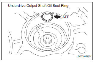
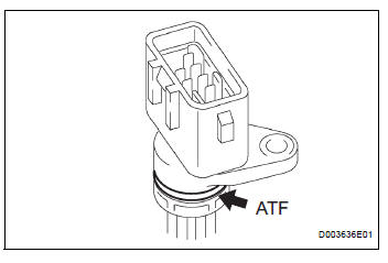
(a) Coat a new oil seal ring with ATF and install it to the transaxle housing.
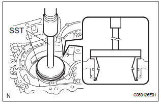
5. INSTALL UNDERDRIVE CYLINDRICAL ROLLER BEARING
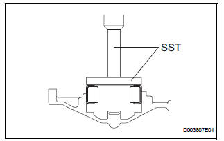
(a) Coat the underdrive cylindrical roller bearing with ATF.
(b) Using SST and a press, install the underdrive cylindrical roller bearing.
SST 09950-60020 (09951-00810), 09950-70010 (09951-07100)
| NOTICE: Do not apply excessive pressure to the bearing. |
6. INSTALL UNDERDRIVE CLUTCH DRUM OIL SEAL RING
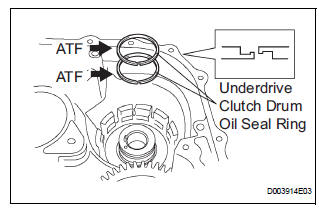
(a) Coat 2 new oil seal rings with ATF, and install them to the transaxle rear cover.
NOTICE:
|
7. INSTALL NEEDLE ROLLER BEARING
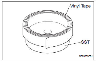
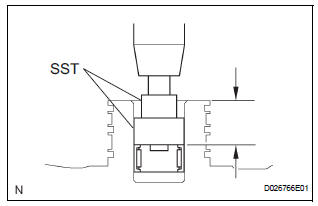
(a) Wrap vinyl tape around the SST 4.0 mm (0.157 in.) from the bottom of the SST until the thickness of the tape is about 5.0 mm (0.197 in.).
SST 09950-60010 (09951-00320), 09950-70010 (09951-07100)
| NOTICE: Clean SST to remove deposited oil, before wrapping vinyl tape. |
(b) Coat the needle roller bearing with ATF.
(c) Using SST and a press, install the needle-roller bearing to the transaxle case.
SST 09950-60010 (09951-00320), 09950-70010 (09951-07100)
| NOTICE: When the wrapped vinyl tape contacts the transaxle case, stop press-fitting. |
8. INSTALL UNDERDRIVE BRAKE PISTON
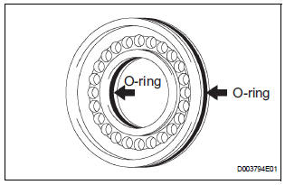
(a) Coat 2 new O-rings with ATF, and install them to the underdrive brake piston.
NOTICE:
|
(b) Coat the underdrive brake piston with ATF.
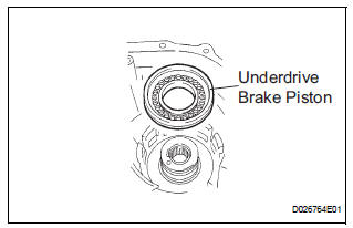
(c) Install the underdrive brake piston to the transaxle case.
| NOTICE: Be careful not to damage the O-ring. |
9. INSTALL UNDERDRIVE BRAKE RETURN SPRING SUB-ASSEMBLY
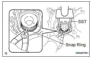
(a) Place SST on the return spring and compress the return spring with a press.
SST 09387-00020 (b) Using a snap ring expander, install the snap ring to the transaxle case.
NOTICE:
|
10. INSTALL BREATHER PLUG NO.2 (ATM)
11. INSTALL COUNTER DRIVE GEAR BEARING
(a) Coat the counterdrive gear bearing with ATF.
(b) Using SST and a press, install the bearing outer race.
SST 09950-60020 (09951-01030), 09950-70010 (09951-07150), 09649-17010
NOTICE:
|
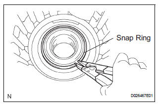
(c) Using a snap ring expander, install the snap ring.
| NOTICE: The white mark side of the snap ring should face upward. |
12. INSTALL COUNTER DRIVE GEAR
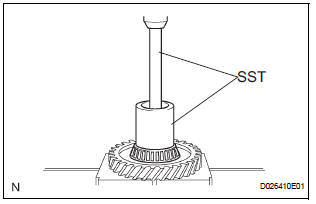
(a) Coat the couterdrive gear with ATF.
(b) Using SST and a press, install the tapered roller bearing to the counter drive gear.
SST 09950-70010 (09951-07150), 09649-17010
| NOTICE: Do not apply excessive pressure to the bearing. |
(c) Using SST and a press, install the counter drive gear and bearing to the transaxle case.
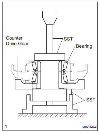
SST 09950-70010 (09951-07150), 09223-15030, 09527-17011, 09950-60020 (09951-00750)
| NOTICE: Do not apply excessive pressure to the counter drive gear. |
13. INSTALL 1ST AND REVERSE BRAKE PISTON
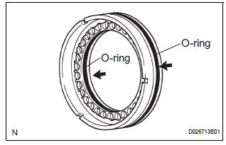
(a) Coat 2 new O-rings with ATF.
(b) Install the 2 O-rings to the 1st and reverse brake piston.
NOTICE:
|
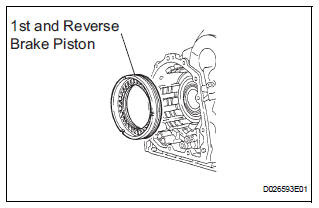
(c) Coat the 1st and reverse brake piston with ATF, and install it to the transaxle case.
| NOTICE: Be careful not to damage the O-ring. |
14. INSTALL 1ST AND REVERSE BRAKE RETURN SPRING SUB-ASSEMBLY
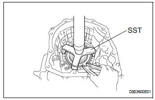
(a) Place SST on the return spring and compress the return spring with a press.
SST 09387-00070
(b) Using a snap ring expander, install the snap ring to the transaxle case.
NOTICE:
|
15. INSTALL FRONT PLANETARY RING GEAR
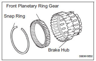
(a) Using a screwdriver, install the front planetary ring gear and snap ring to the brake hub.
| NOTICE: Confirm that the snap ring is engaged in the groove of the brake hub correctly. |
16. INSTALL FRONT PLANETARY GEAR ASSEMBLY
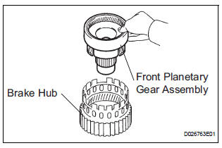
(a) Install the front planetary gear assembly to the brake hub.
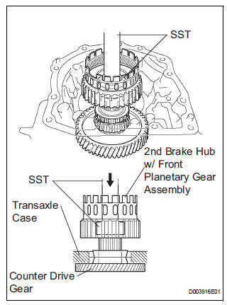
(b) Using SST and a press, press-fit the front planetary gear assembly.
SST 09950-60010 (09951-00500), 09950-70010 (09951-07100)
NOTICE:
|
(c) Install a new washer as shown in the illustration.
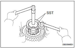
(d) Using SST, install the nut.
SST 09387-00030, 09387-00080 Torque: 280 N*m (3,355 kgf*cm, 207 ft.*lbf)
| NOTICE: Assemble the washer after pressing each part, then tighten the nut to the minimum tightening torque. |
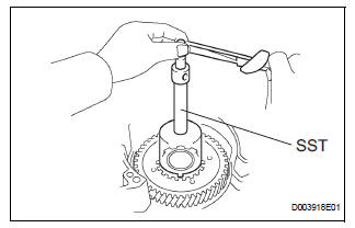
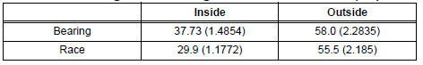
(e) Using SST and a torque wrench, measure the turning torque of the bearing while rotating SST at 60 rpm. When the measured value is not as specified, gradually tighten the nut until it reaches the specified value.
SST 09387-00080
Standard: Turning torque at 60 rpm
Bearing: New Bearing:
0.51 to 1.02 N*m (5.1 to 10.0 kgf*cm, 4.4 to 8.7 in.*lbf) Used Bearing: 0.26 to 0.51 N*m (2.7 to 5.2 kgf*cm, 2.3 to 4.5 in.*lbf)
HINT: Use a torque wrench with a fulcrum length of 160 mm (6.3 in.).
(f) Tighten the nut gradually until the specified turning torque of tapered roller bearing is measured.
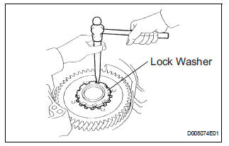
Torque: 350 N*m (3,569 kgf*cm, 258 ft.*lbf) (g) Using a chisel and hammer, stake the front lock washer.
17. INSTALL INPUT SUN GEAR
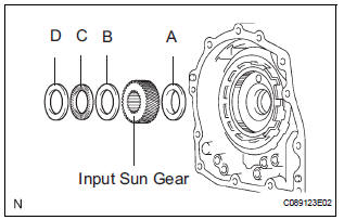
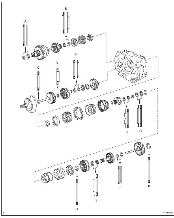
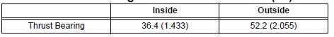
(a) Coat the 2 thrust bearings with ATF.
(b) Install the 2 thrust bearings, the bearing race and the input sun gear to the front planetary gear assembly.
NOTICE:
|
Thrust bearing and bearing race diameter: mm
(in.) 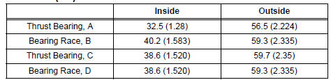
18. INSTALL REAR PLANETARY GEAR ASSEMBLY
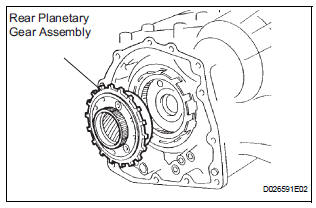
(a) Install the rear planetary gear assembly to the rear planetary ring gear.
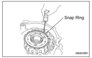
(b) Using a screwdriver, install the snap ring.
| NOTICE: Confirm that the snap ring is fixed in the groove of the 1st and reverse brake hub correctly. |
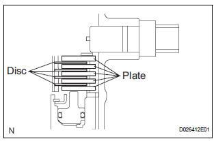
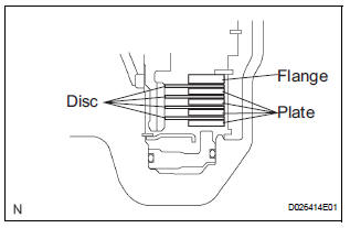
19. INSTALL 1ST AND REVERSE BRAKE CLUTCH DISC
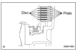
(a) Coat the 6 discs with ATF.
(b) Install the 7 plates and 6 discs.
| NOTICE: Make sure that the plates, discs, and flange are installed as shown in the illustration. |
20. INSPECT PACK CLEARANCE OF FIRST AND REVERSE BRAKE
(a) Using vernier calipers, measure the distance between the disc surface and the contact surface of the 2nd brake cylinder and transaxle case (Dimension A).
(b) Select an appropriate flange so that the pack clearance will meet the specified value.
Pack clearance: 1.16 to 1.35 mm (0.0457 to 0.0531 in.)
HINT: Piston stroke = Dimension A - Flange thickness
Flange thickness: mm (in.) 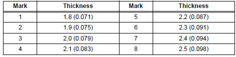
(c) Install the flange.
21. INSTALL SECOND BRAKE PISTON ASSEMBLY
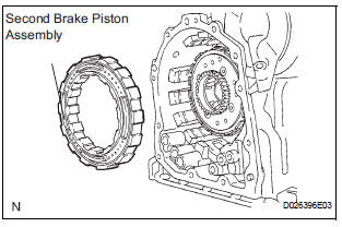
(a) Install the second brake piston assembly to the transaxle case.
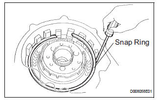
(b) Install the snap ring and measure the inside diameter
Inside diameter: Greater than 167 mm (6.57 in.)
NOTICE:
|
22. INSTALL 1-WAY CLUTCH SLEEVE OUTER
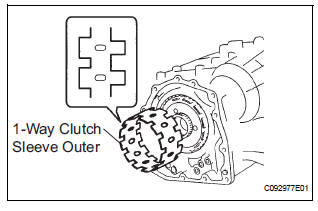
(a) Install the 1-way clutch sleeve outer to the 2nd brake cylinder assembly.
| NOTICE: Make sure that the outer sleeve is installed in the correct direction. |
23. INSTALL 1-WAY CLUTCH ASSEMBLY
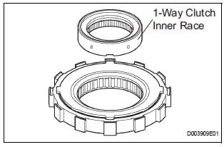
(a) Install the 1-way clutch inner race to the 1-way clutch.
NOTICE:
|
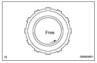
(b) Check the rotating direction of 1-way clutch for the lock or free operation as shown in the illustration.
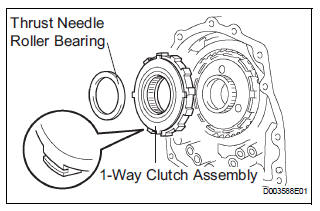
(c) Install the 1-way clutch and thrust needle roller bearing to the 1-way clutch sleeve outer.
Bearing diameter: mm (in.)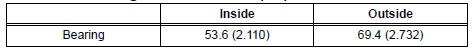
| NOTICE: Install the thrust bearing properly so that nocolored race will be visible. |
24. INSTALL PLANETARY CARRIER THRUST WASHER NO.1
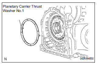
(a) Coat the planetary carrier thrust washer No.1 with yellow petrolatum, and install the washer onto the planetary sun gear assembly.
| NOTICE: After installing, confirm that the projection should be fixed firmly in the hole of the planetary sun gear assembly. |
25. REMOVE REAR PLANETARY SUN GEAR ASSEMBLY
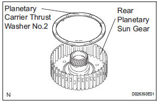
(a) Coat the planetary carrier thrust washer No.2 with yellow petrolatum, and install the washer onto the rear planetary sun gear.
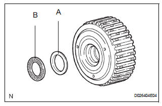
(b) Coat the bearing with yellow petrolatum, and install the bearing onto the rear planetary sun gear.
Bearing diameter: mm (in.) 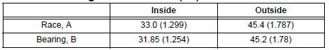
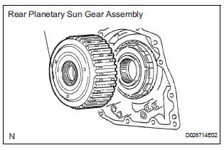
(c) Install the rear planetary sun gear assembly to the rear planetary gear.
| NOTICE: Installing the rear planetary sun gear assembly, make sure that the B1 discs are engaged. |
26. INSTALL 2ND BRAKE CLUTCH DISC
(a) Coat the 4 discs with ATF.
(b) Install the 4 discs and 5 plates to the transaxle case.
(c) Temporarily install the snap ring.
27. INSPECT PACK CLEARANCE OF 2ND BRAKE
(a) Using a vernier calipers, measure the distance between the disc surface and snap ring surface (Dimension B).
(b) Select an appropriate flange so that the pack clearance will meet the specified value.
Clearance: 0.62 to 0.91 mm (0.0244 to 0.0358 in.)
HINT: Piston stroke = Dimension B - Flange thickness - Snap ring thickness 1.6 mm (0.063 in.)
Flange thickness: mm (in.) 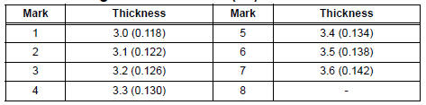
(c) Temporarily remove the snap ring, attach the selected flange and reinstall the snap ring.
| NOTICE: Secure the snap ring so that the ends visible through the groove of the transaxle case. |
28. INSTALL OVERDRIVE DIRECT CLUTCH HUB SUBASSEMBLY
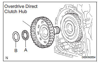
(a) Install the direct clutch hub to the planetary gear assembly.
| NOTICE: Be careful not to damage the bushing inside the overdrive clutch hub during installation. |
(b) Coat the thrust bearing with ATF.
(c) Install the bearing race and the thrust bearing to the direct clutch hub.
NOTICE: Be careful not to drop the bearing when it is installed.
Bearing and race diameter: mm (in.) 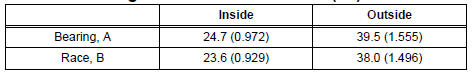
29. INSTALL DIRECT CLUTCH ASSEMBLY
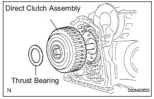
(a) Coat the thrust bearing with ATF.
(b) Install the direct clutch assembly and thrust bearing to the rear planetary sun gear assembly.
| NOTICE: The disc in the direct clutch should completely match with the hub attached outside the rear planetary sun gear. Otherwise, the rear cover cannot be installed. |
(c) Clean the connecting part of the transaxle case and the rear cover.
(d) As shown in the illustration, place a straightedge on the direct clutch drum and measure the distance between the transaxle case and the straightedge using vernier calipers (Dimension C).
(e) Using vernier calipers and a straightedge, measure the dimension shown in the illustration.
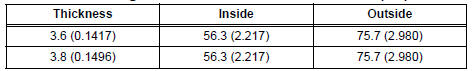
(f) Calculate the end play value using the following formula. Select a thrust bearing which satisfies the end play value and install the selected bearing.
End play: 0.244 to 0.901 mm (0.0096 to 0.0355 in.)
| NOTICE: Make sure that the no-colored race side is facing the direct clutch assembly. |
HINT: End play = Dimension D - Dimension C
Bearing thickness and diameter : mm (in.)
30. INSTALL GOVERNOR APPLY GASKET NO.1
(a) Install 3 new governor apply gaskets No.1 to the transaxle case.
31. INSTALL BRAKE APPLY TUBE
(a) Install the clamp to the brake apply tube.
| NOTICE: Make sure to install the clamp to the apply tube before installing the apply tube to the transaxle case. This prevents the apply tube from being deformed or damaged. |
(b) Install the clutch apply tube.
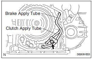
(c) Install the brake apply tube and a bolt to the transaxle case.
Torque: 5.4 N*m (55 kgf*cm, 48 in.*lbf)
| NOTICE: The tube should be securely inserted until it reaches the stopper. |
32. INSTALL NEEDLE ROLLER BEARING
(a) Using SST and a press, press the needle roller bearing into the transaxle rear cover.
SST 09950-60010 (09951-00230, 09952-06010)
Press fit depth: 20.55 to 21.25 mm (0.8091 to 0.8366 in.)
NOTICE:
|
(b) Coat a needle roller bearing with ATF.
33. INSTALL REAR CLUTCH OIL SEAL RING OUTER
(a) Coat 3 new rear clutch oil seal rings with ATF, install them to the transaxle rear cover.
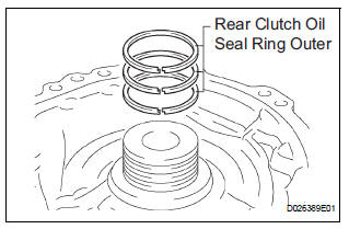
| NOTICE: The snap ring should be fully engaged in the groove of the drum. |
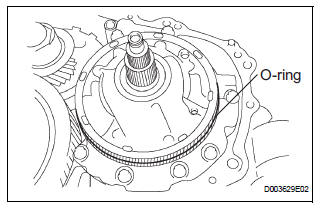
34. INSTALL TRANSAXLE CASE NO.1 PLUG
(a) Coat 4 new O-rings with ATF.
(b) Install the 4 O-rings to the 4 transaxle case No.1 plugs.
(c) Install the 4 transaxle case No.1 plugs to the transaxle rear cover.
Torque: 7.4 N*m (75 kgf*cm, 65 in.*lbf)
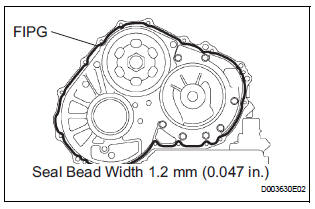
35. INSTALL TRANSAXLE REAR COVER SUBASSEMBLY
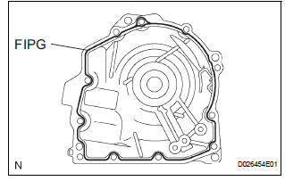
(a) Remove any packing material and be careful not to spill oil on the contact surfaces of the transaxle rear cover or the transaxle case.
(b) Apply FIPG to the cover.
FIPG: Part No. 08826-00090, THREE BOND 1281 or equivalent.
| NOTICE: Make sure that the FIPG is applied in a bead (section diameter: φ1.2) so that the entire sealing surface will be evenly sealed. The FIPG should also protrude slightly from the flange after the assembly of the parts has been completed. |
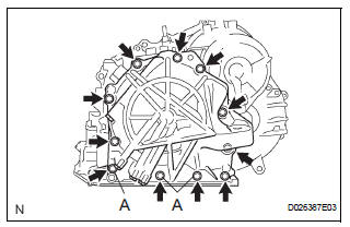
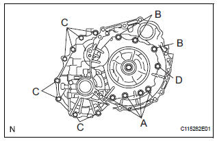
(c) Apply liquid sealer to the "A" bolt threads.
Sealant: Part No. 08833-00080, THREE BOND 1344, LOCTITE 242 or equivalent.
(d) Install the 11 bolts.
Torque: Bolt A 19 N*m (190 kgf*cm, 14 ft.*lbf) Other bolts: 25 N*m (250 kgf*cm, 18 ft.*lbf)
36. INSTALL UNDERDRIVE CLUTCH DISC NO.2
(a) Coat the 4 discs with ATF.
(b) Install the 4 discs, 4 plates and flange to the transaxle case.
| NOTICE: Be careful about the order of discs, plate and flange assembly. |
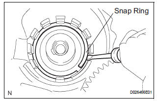
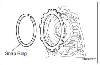
(c) Using a screwdriver, install the snap ring.
| NOTICE: The snap ring should be fully engaged in the groove of the drum. |
37. INSPECT PACK CLEARANCE OF UNDERDRIVE BRAKE
(a) Using a dial indicator, measure the underdrive brake pack clearance while applying and releasing compressed air (392 kPa, 4.0 kgf/cm 2, 57 psi).
Pack clearance: 1.81 to 2.20 mm (0.0713 to 0.0866 in.)
HINT: Select an appropriate flange from the table below so that it will meet the specified value.
Flange thickness: mm (in.)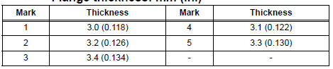
(b) Temporarily remove the snap ring and attach it to the flange.
(c) Reinstall the snap ring.
38. INSPECT UNDERDRIVE 1-WAY CLUTCH ASSEMBLY
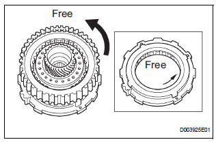
(a) Install the underdrive clutch assembly to the 1-way clutch.
(b) Rotate the underdrive clutch assembly to check the rotating direction for the lock or free operation.
39. INSTALL UNDERDRIVE 1-WAY CLUTCH ASSEMBLY
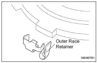
(a) Install the outer race retainer to the 1-way clutch.
| NOTICE: Fix the outer race retainer to the external tooth of the 1-way clutch firmly. |
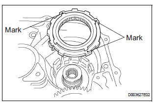
(b) Install the 1-way clutch to the transaxle case.
| NOTICE: Make sure that the mark on the 1-way clutch outer race is visible. |
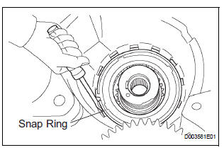
(c) Using a screwdriver, install the snap ring to the transaxle case.
| NOTICE: The snap ring should be fixed fully engaged in the groove of the transaxle case. |
40. INSTALL UNDERDRIVE CLUTCH ASSEMBLY
(a) Coat the bearing and bearing race with petroleum jelly, install them onto the underdrive clutch.
Bearing and bearing race diameter: mm (in.)
(b) Install the underdrive clutch assembly to the transaxle case.
| NOTICE: Do not damage the oil seal when installing the underdrive clutch drum sub-assembly. |
41. INSTALL PARKING LOCK PAWL
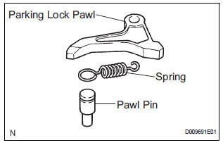
(a) Install the pawl pin and spring to the parking lock pawl.
(b) Temporarily install the parking lock pawl, shaft and spring to the transaxle case, as shown in the illustration.
42. INSTALL UNDERDRIVE PLANETARY GEAR ASSEMBLY
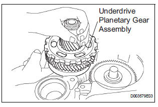
(a) Install the underdrive planetary gear assembly to the transaxle case.
| NOTICE: Fully engage all the discs of underdrive clutch and hub splines of the underdrive planetary gear assembly and install them securely. |
(b) Install the parking lock pawl shaft.
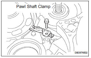
(c) Install the pawl shaft clamp with the bolt.
Torque: 9.8 N*m (100 kgf*cm, 87 in.*lbf)
(d) Using a straightedge and vernier calipers as shown in the illustration, measure the gap between the top of the differential drive pinion in the underdrive planetary gear and the contact surface of the transaxle case and housing (Dimension E).
| NOTICE: Record dimension E for the following process. |
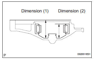
(e) As shown in the illustration, measure the 2 places of the transaxle housing, and calculate dimension F using the formula below.
| NOTICE: Recoad dimension F for the following process. |
HINT: Dimension F = Dimension (1) - Dimension (2)
43. INSTALL MULTIPLE DISC CLUTCH HUB
(a) Install the thrust bearing race No.1 to the transaxle case while checking its direction.
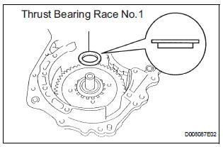
Bearing race diameter: mm (in.)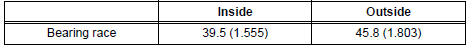
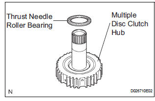
(b) Coat the thrust needle roller bearing and race with yellow petrolatum, install them onto the multiple disc clutch hub.
Thrust bearing and race diameter: mm (in.)
(c) Coat the needle roller bearing with ATF.
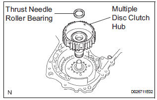
(d) Install the needle roller bearing to the multiple clutch hub.
Bearing diameter: mm (in.) 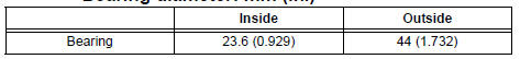
(e) Install the multiple clutch hub to the transaxle case.
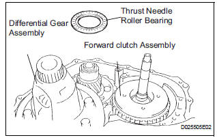
44. INSTALL FORWARD CLUTCH ASSEMBLY
(a) Coat the thrust needle roller bearing with ATF.
(b) Install the thrust needle roller bearing to the forward clutch.
Thrust bearing diameter: mm (in.)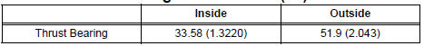
| NOTICE: Install the thrust bearing properly so that the nocolored race or blue ink jet race will be visible. |
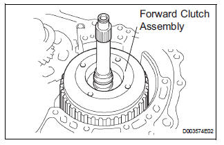
(c) Install the forward clutch to the forward clutch assembly.
NOTICE:
|
45. INSTALL OVERDRIVE BRAKE GASKET
(a) Install 2 new overdrive brake gaskets.
46. INSTALL DIFFERENTIAL GEAR ASSEMBLY
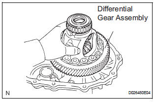
(a) Install the differential gear assembly to the transaxle case.
47. INSTALL THRUST BEARING UNDERDRIVE RACE NO.2
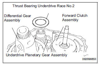
(a) Install the thrust bearing underdrive race No.2 to the underdrive planetary gear assembly.
48. INSTALL THRUST NEEDLE ROLLER BEARING
(a) Coat the thrust needle roller bearing with ATF.
(b) Calculate the end play value using the following formula and values of Dimension E and F that are measured when installing the cylindrical roller bearing and underdrive planetary gear. Select an appropriate underdrive planetary gear thrust bearing race No.2 which satisfies the specified end play value, and install the selected bearing race.
End play: 0.498 to 0.993 mm (0.01961 to 0.03909 in.)
HINT: End play = Dimension F - Dimension E - thrust bearing thickness 2.5 mm (0.0984 in.) - underdrive thrust bearing race No.2 thickness.
Race thickness: mm (in.) 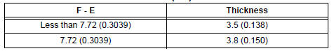
Bearing and bearing race diameter: mm (in.)

49. INSTALL OIL PUMP ASSEMBLY
(a) Install the oil pump to the transaxle case with the 7 bolts.
Torque: 22 N*m (226 kgf*cm, 16 ft.*lbf)
(b) Coat the O-ring of oil pump with ATF.
| NOTICE: Confirm that the input shaft rotates smoothly with the manual operation after installing the oil pump. |
50. INSTALL TRANSAXLE HOUSING
(a) Remove any packing material and be careful not to spill oil on the contact surface of the transaxle case or transaxle housing.
(b) Apply FIPG to the transaxle case.
FIPG: Part No. 08826-00090, THREE BOND 1281 or equivalent
(c) Install the transaxle housing and 16 bolts to the transaxle case.
Torque: Bolt A 22 N*m (225 kgf*cm, 16 ft.*lbf) Bolt B 29 N*m (300 kgf*cm, 22 ft.*lbf) Bolt C 29 N*m (295 kgf*cm, 21 ft.*lbf) Bolt D 22 N*m (226 kgf*cm, 16 ft.*lbf)
HINT: Apply seal packing or equivalent to bolts A and D.
Seal packing: THREE BOND 2403 or equivalent Bolt length Bolt A: 50 mm (1.969 in.) Bolt B: 50 mm (1.969 in.) Bolt C: 42 mm (1.654 in.) Bolt D: 72 mm (2.835 in.)
| NOTICE: Tighten the bolts within 10 minutes of sealant application. |
51. INSPECT INPUT SHAFT END PLAY
(a) Using a dial indicator, measure the input shaft end play.
End play: 0.262 to 1.249 mm (0.0100 to 0.0494 in.)
52. FIX AUTOMATIC TRANSAXLE ASSEMBLY
(a) Fix the transaxle assembly.
53. INSTALL MANUAL VALVE LEVER SHAFT OIL SEAL
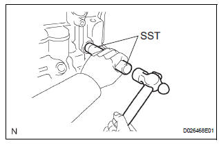
(a) Coat a new oil seal with MP grease.
(b) Install the oil seal to the transaxle case.
SST 09950-60010 (09951-00230), 09950-70010 (09951-07100) Oil seal installation depth: 0 +- 0.5 mm (0 +- 0.197 in. )
54. INSTALL PARKING LOCK ROD SUB-ASSEMBLY
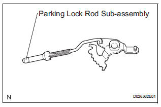
(a) Install the parking lock rod to the manual valve lever.
55. INSTALL MANUAL VALVE LEVER SUB-ASSEMBLY
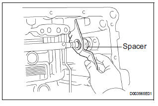
(a) Install a new spacer and manual valve lever shaft to the transaxle case.
| NOTICE: Do not damage the oil seal when installing the shaft to the transaxle case. |
(b) Using a pin punch and hammer, drive in a new pin.
(c) Turn the spacer and the lever shaft to align the small hole for locating the staking position in the spacer with the staking position mark on the lever shaft.
(d) Using a pin punch, stake the spacer through the small hole.
(e) Check that the spacer does not turn.
56. INSTALL MANUAL VALVE LEVER SHAFT RETAINER SPRING
(a) Using needle-nose pliers, install the retainer spring.
| NOTICE: Hang the spring on the shaft firmly. |
57. INSTALL PARKING LOCK PAWL BRACKET
(a) Install the parking lock pawl bracket with the 2 bolts.
Torque: 20 N*m (205 kgf*cm, 15 ft.*lbf) Bolt length: 25 mm (0.984 in.)
| NOTICE: Make sure that the parking rod is placed between the parking pawl and the guide of the parking bracket when the parking bracket is installed. |
58. INSTALL MANUAL DETENT SPRING SUBASSEMBLY
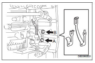
(a) Install the manual detent spring and cover with the 2 bolts.
| NOTICE: Make sure to install the manual detent spring and cover in this order. |
HINT: Tighten bolt A first, and then bolt B.
Torque: Bolt A 20 N*m (205 kgf*cm, 15 ft.*lbf)
Bolt B 12 N*m (120 kgf*cm, 9 ft.*lbf) Bolt length: Bolt A: 27 mm (1.063 in.) Bolt B: 16 mm (0.630 in.)
59. INSTALL B-3 ACCUMULATOR PISTON
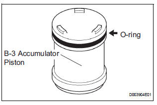
(a) Coat a new O-ring with ATF, install it to the B-3 accumulator piston.
| NOTICE: Make sure that the O-ring is not twisted and that it does not protrude abnormally from the accumulator piston. Apply sufficient ATF before installing the O-ring. The O-ring must be installed in the correct position. |
(b) Coat the piston with ATF, install it to the transaxle case.
| NOTICE: Install the springs to each accumulator piston, checking the identification color or each spring. |
Accumulator spring: 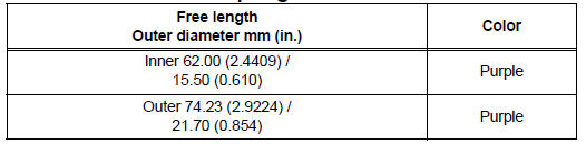
60. INSTALL REVERSE CLUTCH ACCUMULATOR PISTON
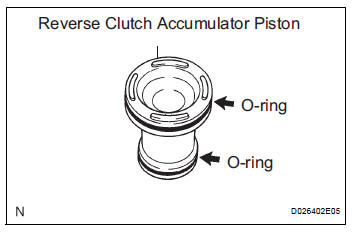
(a) Coat 2 new O-rings with ATF, install them to the reverse accumulator piston.
| NOTICE: Make sure that the O-ring is not twisted and that it does not protrude abnormally from the accumulator piston. Apply sufficient ATF before installing the O-ring. The O-ring must be installed in the correct position. |
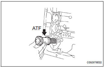
(b) Coat the piston with ATF, install it to the transaxle case.
| NOTICE: Install the springs to each accumulator piston, checking the identification color or each spring. |
Accumulator spring: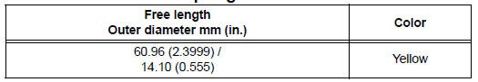
61. INSTALL C-3 ACCUMULATOR PISTON
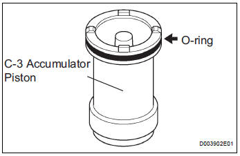
(a) Coat a new O-ring with ATF, install it to the C-3 accumulator piston.
| NOTICE: Make sure that the O-ring is not twisted and that it does not protrude abnormally from the accumulator piston. Apply sufficient ATF before installing the O-ring. The O-ring must be installed in the correct position. |
(b) Coat the piston with ATF, install it to the transaxle case.
| NOTICE: Install the springs to each accumulator piston, checking the identification color or each spring. |
Accumulator spring: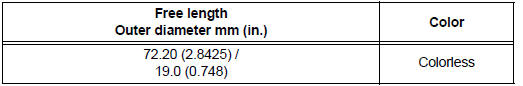
(c) Install the spring to the C-3 accumulator piston.
| NOTICE: Install the springs to each accumulator piston, checking the identification color or each spring. |
62. INSTALL CHECK BALL BODY
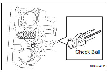
(a) Coat the check ball body with ATF.
(b) Install the check ball body and spring.
| NOTICE: Be sure to place the spring in the hole in the check ball body. Be careful about the direction of the parts. |
63. INSTALL BRAKE DRUM GASKET
(a) Coat a new brake drum gasket with ATF, install it to the transaxle case.
| NOTICE: Be sure not to damage the lip of the transaxle case brake gasket when inserting the gasket to the case. Apply sufficient ATF to the gasket before installation. Be careful about the direction of parts. |
64. INSTALL TRANSAXLE CASE 2ND BRAKE GASKET
(a) Coat a new transaxle case 2nd brake gasket with ATF, and install it to the transaxle case.
| NOTICE: Be sure not to damage the lip of the transaxle case brake gasket when inserting the gasket to the case. Apply sufficient ATF to the gasket before installation. Be careful about the direction of parts. |
65. INSTALL GOVERNOR APPLY GASKET NO.1
(a) Coat a new governor apply gasket No.1 with ATF, and install it to the transaxle case.
| NOTICE: Be sure not to damage the lip of the transaxle case brake gasket when inserting the gasket to the case. Apply sufficient ATF to the gasket before installation. Be careful about the direction of parts. |
66. INSTALL TRANSMISSION WIRE
(a) Coat a new O-ring with ATF, and install it to the transmission wire.
| NOTICE: Make sure that the O-ring is not twisted, protruded, or pinched when installing the wire transmission to the transaxle case. Apply sufficient ATF to the O-ring before installation. |
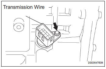
(b) Install the transmission wire retaining bolt.
Torque: 5.4 N*m (55 kgf*cm, 48 in.*lbf)
67. CONNECT TRANSMISSION WIRE
(a) Coat an O-ring of the ATF temperature sensor with ATF.
(b) Install the ATF temperature sensor with the lock plate and bolt.
Torque: 6.6 N*m (67 kgf*cm, 58 in.*lbf) (c) Connect the 7 solenoid connectors.
NOTICE:
|
68. INSTALL TRANSMISSION VALVE BODY ASSEMBLY
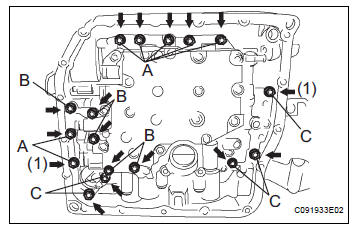
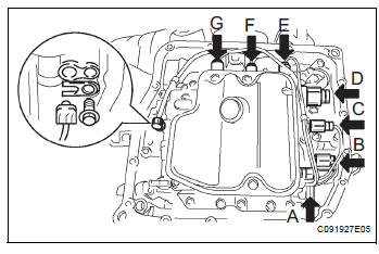
(a) While positioning the manual valve lever position, install the valve body to the transaxle case with the 17 bolts.
Torque: 11 N*m (110 kgf*cm, 8 ft.*lbf) Bolt length: Bolt A: 41 mm (1.614 in.) Bolt B: 57 mm (2.244 in.) Bolt C: 25 mm (0.984 in.)
NOTICE:
|
69. INSTALL VALVE BODY OIL STRAINER ASSEMBLY
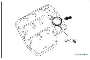
(a) Coat a new O-ring with ATF and install it to the oil strainer.
| NOTICE: Make sure that the O-ring is not twisted or pinched. Apply sufficient ATF to the O-ring before installation. |
(b) Install the oil strainer and 3 bolts to the valve body.
Torque: 11 N*m (110 kgf*cm, 8 ft.*lbf)
| NOTICE: Apply ATF to the bolts. |
70. INSTALL AUTOMATIC TRANSAXLE OIL PAN SUBASSEMBLY
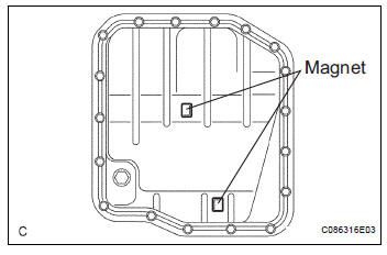
(a) Install the 2 magnets to the oil pan.
(b) Apply seal packing or equivalent to new 18 bolts.
Seal packing: THREE BOND 2430 or equivalent
(c) Install the oil pan and new oil pan gasket to the transaxle case with the 18 bolts.
Torque: 7.8 N*m (80 kgf*cm, 69 in.*lbf)
NOTICE:
|
71. INSTALL TRANSAXLE CASE NO.1 PLUG
(a) Coat 4 new O-rings with ATF, and install them to the 4 transaxle case No.1 plugs.
(b) Install the 4 transaxle case No.1 plugs to the transaxle case.
Torque: 7.4 N*m (75 kgf*cm, 65 in.*lbf)
72. INSTALL SPEED SENSOR
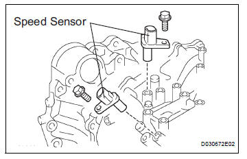
(a) Coat 2 new O-rings with ATF and install them to the 2 sensors.
(b) Install the 2 sensors to the transaxle case with the 2 bolts.
Torque: 11.0 N*m (115 kgf*cm, 8 ft.*lbf)
73. INSTALL OIL COOLER TUBE UNION (OUTLET OIL COOLER UNION)
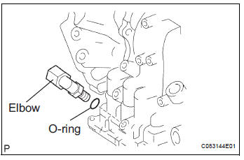
(a) Coat a new O-ring with ATF, and install it to the elbow.
(b) Install the elbow to the transaxle case.
Torque: 27 N*m (276 kgf*cm, 20 ft.*lbf)
74. INSTALL OIL COOLER TUBE UNION (INLET OIL COOLER UNION)
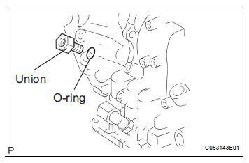
(a) Coat a new O-ring with ATF, and install it to the union.
(b) Install the union to the transaxle case.
Torque: 25 N*m (255 kgf*cm, 18 ft.*lbf)
75. INSTALL BREATHER PLUG HOSE
(a) Install the breather plug hose to the transaxle case firmly.
76. INSTALL PARK/NEUTRAL POSITION SWITCH ASSEMBLY
(a) Install the park/neutral position switch onto the manual valve lever shaft, and temporarily install the 2 adjusting bolts.
(b) Install a new nut stopper and nut.
Torque: 6.9 N*m (70 kgf*cm, 61 in.*lbf)
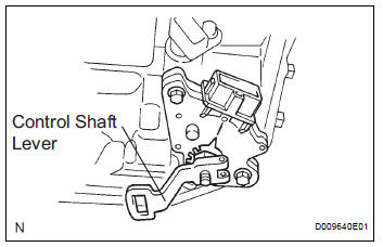
(c) Temporarily install the control shaft lever.
(d) Turn the lever counterclockwise until it stops, and then turn it clockwise 2 notches.
(e) Remove the control shaft lever.
(f) Align the groove with the neutral basic line.
(g) Tighten the 2 bolts.
Torque: 5.4 N*m (55 kgf*cm, 48 in.*lbf)
(h) Using a screwdriver, stake the nut with the nut stopper.
(i) Install the control shaft lever, washer and nut.
Torque: 13 N*m (130 kgf*cm, 9 ft.*lbf)
77. INSTALL SPEEDOMETER DRIVEN HOLE (ATM) COVER SUB-ASSEMBLY
(a) Coat a new O-ring with ATF and install it to the speedometer driven hole cover.
(b) Install the bolt and speedometer driven hoke cover sub assembly to the transaxle assembly.
Torque: 6.9 N*m (70 kgf*cm, 61 in.*lbf)
 Inspection
1. INSPECT MULTIPLE DISC CLUTCH HUB
(a) Using a dial indicator, measure the inside diameter
of the forward clutch hub bushing
Standard inside diameter:
23.025 to 23.046 mm (0.9065 to 0.9073 in ...
 Oil pump
COMPONENTS
...
Other materials:
Crankshaft Position - Camshaft Position Correlation
DTC P0016 Crankshaft Position - Camshaft Position Correlation
(Bank 1 Sensor A)
DTC P0017 Crankshaft Position - Camshaft Position Correlation
(Bank 1 Sensor B)
DTC P0018 Crankshaft Position - Camshaft Position Correlation
(Bank 2 Sensor A)
DTC P0019 Crankshaft Position - Camshaft Position Corr ...
Removal
1. REMOVE REAR WHEEL
2. REMOVE SKID CONTROL SENSOR WIRE (for 2WD)
(a) Disconnect the skid control sensor connector.
(b) Remove the bolt and disconnect the bracket from
the rear axle beam assembly.
HINT:
Separate the RH side by the same procedures as
the LH side.
3. SEPARATE SPEED SENSO ...
ECM / PCM Internal Engine Off Timer Performance
DTC P2610 ECM / PCM Internal Engine Off Timer Performance
DTC SUMMARY
DESCRIPTION
To ensure the accuracy of the EVAP (Evaporative Emission) monitor values, the
soak timer, which is built
into the ECM, measures 5 hours (+/- 15 minutes) from when the ignition switch is
turned off, before t ...
