Toyota Sienna Service Manual: Reassembly
1. INSTALL INPUT SHAFT OIL SEAL RING
(a) Compress a new input shaft oil seal ring from both sides to reduce dimension A.
Dimension A: 5 mm (0.197 in.)
(b) Coat the oil seal ring with ATF and install it to the input shaft.
NOTICE: Do not expand the end gap of the oil seal ring too much. Fix the hooks firmly.
2. INSTALL FORWARD CLUTCH PISTON SUBASSEMBLY
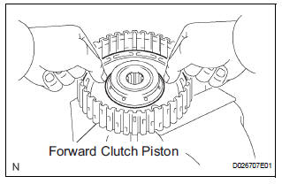
(a) Coat the forward clutch piston with ATF, and install it to the input shaft.
NOTICE: Be careful not to damage the lip of the forward clutch piston.
3. INSTALL FORWARD CLUTCH RETURN SPRING SUB-ASSEMBLY
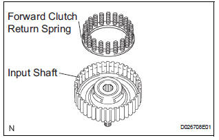
(a) Install the return spring to the input shaft.
NOTICE: Installing the spring sub-assembly, check that all of the springs are fit in the piston correctly.
(b) Coat the clutch balancer with ATF.
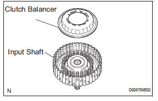
(c) Install the clutch balancer to the input shaft.
NOTICE:
- Be careful not to damage the lip of the forward clutch balancer.
- Make sure that the clutch balancer is not pinched and that there are no other defects at the lip.
- Apply sufficient ATF to the sealing lip before installation.
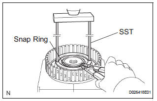
(d) Place SST on the clutch balancer, and compress the clutch balancer with a press.
SST 09387-00020
(e) Install the snap ring with a snap ring expander.
(f) Be sure that the end gap of the snap ring is not aligned with the spring retainer claw.
NOTICE:
- Stop the press when the spring seat is lowered to the place 1 to 2 mm (0.039 to 0.078 in.) from the snap ring groove.
- This prevents the spring seat from being deformed.
- Do not expand the snap ring excessively.
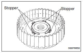
(g) Set the end gap of the snap ring in the piston as shown in the illustration.
NOTICE: The end gap of the snap ring should not align with any of the stoppers.
4. INSTALL FORWARD MULTIPLE DISC CLUTCH DISC
(a) Coat the 5 discs with ATF.
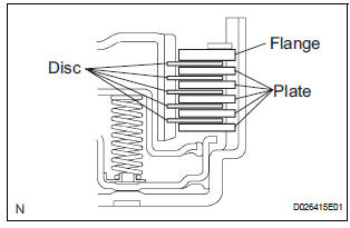
(b) Install the 5 plates, 5 discs and flange input shaft.
NOTICE: Make sure that the plates, discs, and flange are installed as shown in the illustration.
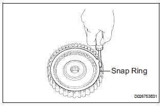
(c) Using a screwdriver, install the snap ring.
(d) Check that the end gap of the snap ring is not aligned with one of the cutouts.
NOTICE: The snap ring should be fully engaged in the groove of the drum.
5. INSPECT PACK CLEARANCE OF FORWARD CLUTCH
HINT: (See page AX-243)
6. INSPECT FORWARD MULTIPLE DISC CLUTCH DISC
HINT: (See page AX-243)
 Inspection
1. INSPECT PACK CLEARANCE OF FORWARD CLUTCH
(a) Install the forward clutch on the oil pump.
NOTICE:
Be careful not to damage the oil seal ring of oil
pump.
b) Using a dial indicator, measure ...
 Direct clutch
Components
...
Other materials:
Rear Occupant Classification Sensor RH Collision
Detection
DTC B1788 Rear Occupant Classification Sensor RH Collision
Detection
DESCRIPTION
DTC B1788 is output when the occupant classification ECU receives a collision
detection signal sent by
the rear occupant classification sensor RH if an accident occurs.
DTC B1788 is also output when the front s ...
If your vehicle has to
be stopped in an
emergency
Only in an emergency, such as if it becomes impossible to stop
the vehicle in the normal way, stop the vehicle using the following
procedure:
Steadily step on the brake pedal with both feet and firmly depress it.
Do not pump the brake pedal repeatedly as this will increase the effort
requi ...
Removal
1. REMOVE REAR WINDOW SIDE GARNISH
ASSEMBLY
2. REMOVE REAR DOOR WINDOW FRAME SUBASSEMBLY
3. REMOVE SIDE TRIM BOARD COVER REAR
4. REMOVE REAR DOOR TRIM BOARD SUBASSEMBLY
5. REMOVE REAR DOOR GLASS RUN
6. REMOVE SLIDE DOOR WINDOW ASSEMBLY
7. REMOVE REAR DOOR GLASS WEATHERSTRIP
Put pro ...
